5
63-2483—2
ML6185
INSTALLATION
4. Remove the mounting bracket and actuator.
5. Drill or center punch the starting holes for the mount-
ing bracket screws (or use no. 10 self-tapping sheet metal
screws).
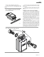
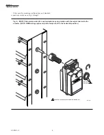
Fig. 2—Installing mounting bracket on ML6185
Direct Coupled Actuator.
6. Place the actuator and mounting bracket back into
position over the damper shaft and install the mounting
bracket screws.
7. Tighten the two 8 mm x 12 mm long set screws firmly
against the damper shaft (maximum tightening torque is
100 lb-in.).
Installing the Actuator for Three-Point Mounting
The ML6185 Direct Coupled Actuator is designed with
removable hub sleeves to accommodate specific damper
shaft sizes. Proper sleeve selection is necessary when three-
point mounting is used to avoid excessive strain on the
output gear. Most ML6185 Actuators are shipped with a
1/2 in. hub sleeve. For field use, several hub sleeve sizes are
available. See the Accessories listing in the Specifications
section. Shaft sizes are stamped on the sleeves.
The ML6185 Direct Coupled Actuator can be mounted
directly on the motor shaft with the actuator in any position
when the actuator housing is parallel with the damper
housing or frame. (See Fig. 7.)
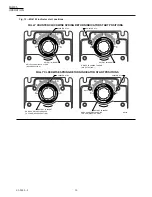
The ML6185 Direct Coupled Actuator has a reversible
output hub. The hub is factory mounted on the top of the
actuator gear housing. When attaching to damper shafts
less than 3.5 in. (76 mm) long, or for ease of mounting, the
output hub can be mounted to the inside of the actuator gear
housing. See Fig. 3. Be careful when removing the retain-
ing ring that secures the output hub to the actuator housing.
Use a flatheaded screwdriver to pry the ring loose.
60
30
90
M9386
.500
.500
30
30
0
60
60
90
M7228
1
6
4
5
2
3
DETENT
INSERT
INDICATOR
DETENTS
Fig. 3—Mounting hub to inside of actuator.

