


|
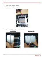
33
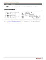
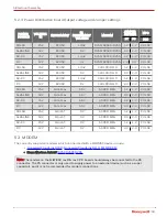
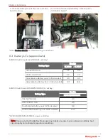
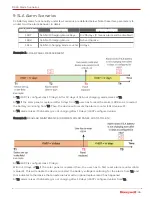
5.2.3 Power Distribution board Output voltage and Jumper settings
POWER
SOURCE
VOLTAGE
IN
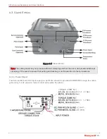
INSTRUMENT
S1
INSTRUMENT
VOLTAGE
MODEM
JUMPER
SETTING
P7
P8
MPC
P10
SOLAR
15V
EC350
13.4V
RV50/RV50X/RV55
1-2
1-2
PULSE
ALKALINE
18V
EC350
9V
RV50/RV50X/RV55
2-3
2-3
PULSE
AC-DC
15V
EC350
13.4V
RV50/RV50X/RV55
1-2
1-2
PULSE
DC
12V
EC350
9V
RV50/RV50X/RV55
2-3
2-3
PULSE
SOLAR
15V
EC350
13.4V
CLR100/R110
1-2
1-2
PULSE
ALKALINE
18V
EC350
9V
CLR100/R110
2-3
2-3
PULSE
AC-DC
15V
EC350
13.4V
CLR100/R110
1-2
1-2
PULSE
DC
12V
EC350
9V
CLR100/R110
2-3
2-3
PULSE
SOLAR
15V
Mini-Max
6.5V
AS PER MSG
1-2
1-2
PULSE
ALKALINE
18V
Mini-Max
6.5V
AS PER MSG
2-3
2-3
PULSE
AC-DC
15V
Mini-Max
6.5V
AS PER MSG
1-2
1-2
PULSE
DC
12V
Mini-Max
6.5V
AS PER MSG
2-3
2-3
PULSE
SOLAR
15V
Mini-AT
9V
AS PER MSG
1-2
1-2
PULSE
ALKALINE
18V
Mini-AT
9V
AS PER MSG
2-3
2-3
PULSE
AC-DC
15V
Mini-AT
9V
AS PER MSG
1-2
1-2
PULSE
DC
12V
Mini-AT
9V
AS PER MSG
2-3
2-3
PULSE
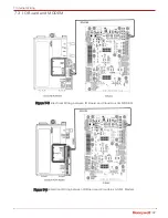
5.3 MODEM
The currently supported modems which can be used with a MIWI350 device include:
•
Honeywell CloudLink R110-M1 MODEM
• Sierra Wireless AirLink®
Note:
The modem on the MIWI350 rev B & rev C PD board should always be connected to the P6
connector. The P5 connector is only used to supply power to an external device (such as a super
capacitor), and it is not recommended for modem connections.
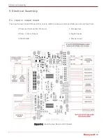
5 Electrical Assembly