


|
27
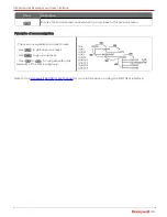
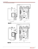
Figure 4-11: Temperature Input
GLAND
DESCRIPTION
Pulse Input
The UMB/Remote pulse inputs (as per MSG) should be provided to
MIWI350 through this cable gland only.
Pulse Output
To utilize the 3x Pulse output & 1x Alarm output , the wiring has to be
done and cables should be routed through this cable gland only.
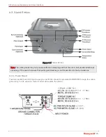
Remote Antenna (Optional)
Honeywell approved remote antenna cable for MIWI350 Modem
should be provided through this N-Type RF Connector. The MIWI350
comes along with the RF connector when this remote antenna option
is selected in MSG.
Case Connector (Optional)
The MIWI350 Power/communication variants has support for case
connector to provide the modem serial communication interface.
MIWI350 will come with case connector when this option is selected
in MSG
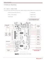
Instruction for Grounding:
The ground terminal shall be connected to an earth-ground using 12AWG or higher wire gauge and the
insulation shall have flammability rating of UL94 V-2 or better. The color code and wiring shall be done as
per the rule by the National Electrical Code.
Caution:
2X Breather (Bottom) & 1X Breather (Side) vents provided to allow the air passage for
pressure equalization, prevent moisture intrusion and protect the device from ingress. Should neither
be closed nor used for any cable routing purposes.
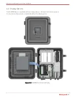
4 Mechanical Assembly and User Interface