6
ENGLISH
IMPORTANT SAFETY INSTRUCTIONS
1. Before using this appliance, read through all the instructions
and only use accordingly.
2. This appliance is not intended for use by persons (including
children) with reduced physical, sensory or mental
capabilities, or lack of experience and knowledge, unless
they have been given supervision or instruction concerning
use of the appliance by a person responsible for their safety.
Children should be supervised to ensure that they do not play
with the appliance.
3. The appliance is intended only for use indoors, not for
outdoor use or commercial use.
4. Do not use the appliance anywhere near easily flammable
gases or substances such as solvents, lacquers, glues, etc.
Some of the internal parts can be hot and could throw sparks.
5. Do not position the appliance immediately below a power
socket.
6. Keep flammable materials at least 100cm away from the
heater. To prevent burns, do not allow bare skin to come in
contact with hot surfaces.
7.
Do not cover the appliance with anything, as indicated
by the symbol. This can lead to overheating, fire or electric
shocks. Ensure that the air intake and outlet vents are not
obstructed.
8. Do not use this appliance or the power cord if it is damaged
or shows signs of damage, or does not function properly.
Repairs must be carried out by manufacturer-approved
service centres.
9. Never touch the unit with wet hands.
10. The electrical installation which is to be connected must
conform with local regulation requirements.
11. Ensure that the unit is not accessible from the shower or
bathtub.
12. This unit has an IP24 protection level and is suitable for use
in bathrooms excluding Zones 1 & 2.
13. The panel may become very hot therefore caution is advised
when touching the unit while in operation.
14 In the event of overheating, the safety device on the
appliance automatically disables the heating elements. The
product will resume automatic operation as soon as the
temperature returns below the safety limit
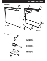
COMPONENTS
1. Air Outlet Grille
2. Air Inlet Grille
3. Control Box
4. Upper Mounting Rail
5. Lower Mounting Rail
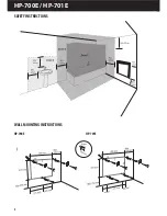
WALL MOUNTING INSTRUCTIONS
For wall mounting details please refer to page 4 and 5 and follow
the instructions carefully. Not doing so may result in an instable
product.
Screws and brackets for mounting are included with the unit.
Only use the product in a horizontal position so that the air outlet
grille is at the top.
Never install the product on a surface made from wood or
synthetic material.
Always ensure that minimum distances are adhered to - see page 4.
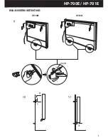
One of the upper wall mounting brackets must be positioned
inside the control panel on the rear of the unit as indicated in
picture “
II
”.
Ensure that the lower mounting brackets on the bottom of the
unit are positioned in two different slots and not in the same one.
See detail of picture “
II
” on page 5
ELECTRICAL CONNECTION
Connect the product to the mains power supply using a 3-wire
cable (Brown=Live, Blue=Neutral, Black=Pilot wire) and a
connection box.
If you do not wish to use the pilot wire functions, connect the
phase and the neutral wires.
In bathrooms, kitchens or other humid areas, install the
connection terminal at least 25cm off the floor.
The electrical connection to the mains power supply must also
include a 2-pole switch with a minimum contact aperture of 3mm.
If the product is powered through a 30mA differential switch, make
sure the pilot wire is also controlled by the differential switch.
CONTROL PANEL
1. Power light
Red light indicates the product has not yet reached the
desired temperature. Orange light indicates the product has
reached the desired temperature. A flashing light indicates a
defective electronic sensor. The product needs to be repaired
by an authorised dealer.
2. Temperature Control
The temperature range lies between 10°C and 30°C. The
optimum combination between room temperature and
power consumption is indicated by the “comfort zone”. To
additionally use the frost watch function, ensure that this
function is chosen on the settings panel.
6. Power Cord
7. Upper Mounting Bracket
8. Lower Mounting Bracket
9. Screws and Dowels
L
N
Phase (brown)
Pilot wire (black)
Neutral (blue)
Do Not Connect to Earth
Summary of Contents for HP-700E
Page 3: ... HP 700E HP 701E Front View Rear View Mounting parts COMPONENTS ...
Page 4: ... SAFETY INSTRUCTIONS HP 700E HP 701E HP 700E HP 701E WALL MOUNTING INSTRUCTIONS ...
Page 5: ... HP 700E HP 701E WALL MOUNTING INSTRUCTIONS HP 701E HP 700E ...
Page 26: ...26 ...
Page 27: ...27 ...
Page 34: ...34 NOTES ...
Page 35: ...35 NOTES ...


