3
69-1585
The heat anticipator can require further adjustment
for best performance. To lengthen burner-on time, move
the indicator in the direction of the longer arrows—not
more than one-half scale marking at a time. To shorten
burner-on time, move indicator in opposite direction.
Most one-stage heating equipment is designed to
operate at five to six cycles per hour, at 50 percent load
conditions. When using this thermostat in heat pump
systems, set the heat anticipator at 140 percent of the
actual primary control current draw to reduce the cy-
cling rate. Most heat pump systems should cycle 2-1/2 to
3 times per hour.
Checkout
CAUTION
Do not check operation by shorting across ter-
minals of system controls. This will damage
the heat anticipator.
IMPORTANT: To assure accurate temperature con-
trol, do not touch or breathe on bimetal or ther-
mometer.
HEATING
With system switch set at HEAT and fan switch at
AUTO, move the temperature setting lever about 10
°
F
(6
°
C) above room temperature. In standard systems,
heating should start; fan should start after a short delay.
In heat pump or electric heat systems, both heating and
fan should start.
Move temperature setting lever about 10
°
F (6
°
C) be-
low room temperature. In standard systems, heating
should shut off and fan should shut off after a short
delay. In heat pump or electric heat systems, both heat-
ing and fan should shut off.
COOLING
CAUTION
Do not operate cooling if outdoor temperature
is below 50
°
F (10
°
C). Refer to manufacturer
recommendations.
NOTE: To prevent compressor short cycling, some manu-
facturer equipment includes a minimum off-timer to
provide a five-minute time delay before activating
the compressor when the thermostat last turned the
compressor off, or from when the system first re-
ceived power. This delay protects the compressor.
With the system switch set at COOL and fan switch at
AUTO, move the temperature setting lever about 10
°
F
(6
°
C) below room temperature. Cooling and fan should
start (see NOTE above). Move the temperature setting
lever about 10
°
F (6
°
C) above room temperature. Cool-
ing and fan should shut off.
FAN
With the system switch set at OFF, and the fan switch
at ON, the fan should run continuously. Move the fan
switch to AUTO. In standard systems, fan operation is
controlled by the plenum fan control in heating and by
the thermostat in cooling. In heat pump or electric heat
systems, fan operation is controlled by the thermostat in
heating and cooling.
RECALIBRATION
These thermostats are calibrated at the factory and
should not need recalibration. If the thermostat seems
out of adjustment, first check for accurate leveling.
To check calibration, proceed as follows:
1. Move the temperature setting lever to the lower
end of the temperature scale. System switch must be
placed OFF. Wait at least five minutes.
2. Remove the thermostat cover. Move the setting
lever until the switch just makes contact. The mercury in
the switch will roll to the left end of the tube.
3. Replace cover and wait five minutes for the cover
and the thermostat to lose the heat it has gained from
your hands. If the thermometer pointer and the setting
lever indicator read approximately the same, no
recalibration is needed.
If recalibration appears necessary, proceed as fol-
lows:
1. Place the temperature setting lever at the same
setting as the thermometer. Remove cover by pulling
outward on right edge of cover until it snaps free of the
thermostat base.
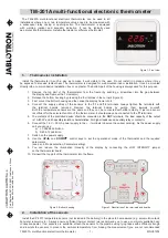
2. Insert Honeywell 104994A Calibration Wrench
(ordered separately) onto the hex nut under the coil. See
Fig. 3. Holding the setting lever so it does not move, turn
the wrench clockwise
until the mercury rolls to
the right end of the tube. Remove wrench and replace
cover.
To assure accurate temperature control, do not touch
or breathe on bimetal or thermometer.
3. Move the setting lever to a low setting. Wait at
least five minutes for temperature to stabilize.
4. Slowly move the setting lever until it reads the
same as the thermometer.
5. Remove cover. Holding the setting lever so it does
not move, reinsert wrench and carefully turn counter-
clockwise
until the mercury rolls to the left end
of the tube but no farther.
6. Recheck calibration. Set the thermostat system
switch for desired operation and replace cover.
Fig. 3—Recalibration procedure.
CALIBRATION
WRENCH
COIL SHOWN WITHOUT
HEAT ANTICIPATOR
M2044