background image

15   

HD273H(X) Minidome Camera User Guide 

800-18606  –  A  –  06/2014 


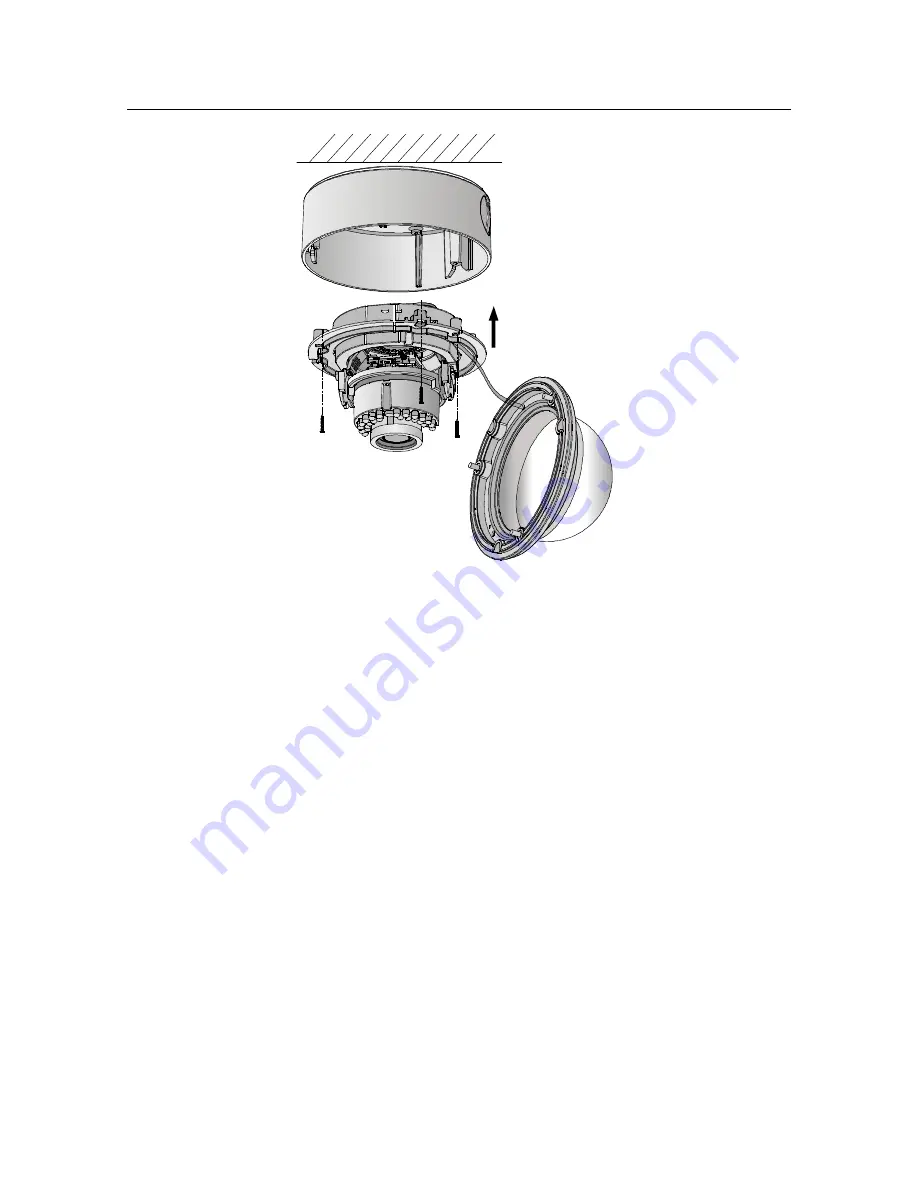
Figure 1-5   Aligning the Camera 

7.  Connect the video output (BNC) connector to the monitor. 

Connect the power connector to the power supply. 

8.  Adjust the image and focus. Please refer to the

 Adjusting 

the Image and Focus section on page 23

 for more details. 

9.  Fit the black liner back onto the camera (see Figure 1-6). 

Summary of Contents for HD273H

Page 1: ...800 18606 A 06 2014 Performance Series HD273H X True Day Night Outdoor Fixed Minidome with IR LEDs User Guide ...

Page 2: ...th the limits for a Class B digital device pursuant to part 15 of the FCC Rules These limits are designed to provide reasonable protection against harmful interference in a residential installation This equipment generates uses and can radiate radio frequency energy and if not installed and used in accordance with the instructions may cause harmful interference to radio communications However ther...

Page 3: ...eil numérique de la Classe B est conforme à la norme NMB 003 du Canada EU Conformity Statement This product and if applicable the supplied accessories comply with the applicable harmonized European standards listed under the Low Voltage Directive 2006 95 EC the EMC Directive 2004 108 EC the RoHS Directive 2011 65 EU 2012 19 EU WEEE directive Products marked with this symbol cannot be disposed of a...

Page 4: ... or equipment damage may occur if any of the cautions are neglected Warnings WARNING Installation and servicing should be performed only by qualified and experienced technicians to conform to all local codes and to maintain your warranty WARNING This device is configured for 24 V AC or 12 V DC operation Do not connect to a higher voltage Use only with NRTL approved Class 2 or LPS power supplies Wa...

Page 5: ...mportant Safety Instructions Read and keep these instructions Ensure that your installation area can safely support 3 times the weight of the camera Do not install the camera in extreme temperature conditions Only use the camera where temperatures are within the limits shown in the camera specifications Be especially careful to provide ventilation when operating under high temperatures Do not inst...

Page 6: ...a User Guide 800 18606 A 06 2014 Do not use strong or abrasive cleaners clean only with a soft cloth and mild detergent or alcohol Do not open the camera or attempt to service it yourself Refer all service issues to your dealer ...

Page 7: ...ting the Camera on a Ceiling 12 In ceiling Mounting the Camera 17 In ceiling Mounting the Camera with a Gang Box 20 Adjusting the Image and Focus 23 Menu Description 25 AE Auto Exposure 26 BRIGHTNESS 27 AE MODE 27 AGC 27 SENSE UP 28 WB 28 AUTO 28 MANUAL 28 DAY NIGHT 29 COLOR 29 B W 29 SMART 29 VIDEO SETTING 30 SCREEN RATIO 31 CONTRAST 31 SHARPNESS 31 ...

Page 8: ...8 HD273H X Minidome Camera User Guide 800 18606 A 06 2014 COLOR GAIN 32 3D NR 32 MIRROR 32 FUNCTION 33 DETECTION 33 MASKING 36 ZOOM IN 38 LANGUAGE 38 RESET 38 SAVE EXIT 38 ...

Page 9: ...s follows High performance CMOS sensor supplies high resolution high quality images Low illumination 0 1 Lux F1 2 AGC ON 0 Lux with IR LEDs on IR cut filter with automatic switching OSD menu parameters are configurable Auto white balance auto gain control electronic shutter control and internal synchronization Advanced Engineering Design and patented universal adjustable structure provides conveni...

Page 10: ...User Guide 800 18606 A 06 2014 Overview Figure 1 1 Overview of Camera Table 1 1 Description No Description No Description 1 Auxiliary Video Output 5 Back Box 2 Menu Button 6 Power Cable 3 Black Liner 7 Video Cable 4 Lens 8 Bubble ...

Page 11: ...e ensure the power supply voltage matches your camera requirements Please make sure the installation surface is strong enough to withstand three times the weight of the camera and the mounting If the installation surface is concrete you need to insert expansion screws before you install the camera If the installation surface is wood you can use self tapping screws to secure the camera If the produ...

Page 12: ...ere is no reflective surface too close to the camera lens The IR light from the camera may reflect back into the lens and obscure the image The foam ring around the lens must be seated flush against the inner surface of the bubble to isolate the lens from the IR LEDs Fasten the dome cover to the camera body so that the foam ring and the dome cover are seamlessly connected Surface Mounting the Came...

Page 13: ...6 2014 Figure 1 2 HD273H X Mounting Template 2 Loosen the three screws on the edge of the bubble with the supplied screwdriver to remove the bubble and the black liner 3 Remove the camera from the back box Figure 1 3 Removing the Camera from the Back Box ...

Page 14: ...g the holes of the back box with the holes drilled in step 1 and secure it to the ceiling wall with the supplied screws see Figure 1 4 Figure 1 4 Securing the Back Box 5 Route the cables through the cable hole 6 Align the camera with the back box and tighten the set screws to secure the camera with the back box ...

Page 15: ... Camera 7 Connect the video output BNC connector to the monitor Connect the power connector to the power supply 8 Adjust the image and focus Please refer to the Adjusting the Image and Focus section on page 23 for more details 9 Fit the black liner back onto the camera see Figure 1 6 ...

Page 16: ...16 HD273H X Minidome Camera User Guide 800 18606 A 06 2014 Figure 1 6 Fitting the Black Liner 10 Tighten the screws to secure the bubble with the back box Figure 1 7 Securing the Bubble ...

Page 17: ...d to purchase an in ceiling mount separately if your installation requires an in ceiling mounting Steps 1 Attach the mounting template supplied to the place where you want to install the camera and then drill the screw holes and cable hole in the ceiling according to the mounting template 2 Secure the in ceiling mount with two mounting screws as shown in Figure 1 8 Figure 1 8 Securing the In ceili...

Page 18: ...ra with the in ceiling mount Figure 1 9 Securing the Camera 5 Connect the video output BNC connector to the monitor Connect the power connector to the power supply 6 Adjust the image and focus Please refer to the Adjusting the Image and Focus section on page 23 for more detailed information 7 Fit the black liner back onto the camera see Figure 1 10 ...

Page 19: ...Camera User Guide 800 18606 A 06 2014 Figure 1 10 Fitting the Black Liner 8 Align the bubble with the in ceiling mount and then tighten the screws to secure the bubble to the in ceiling mount Figure 1 11 Aligning the Bubble ...

Page 20: ...ches during the installation process In ceiling Mounting the Camera with a Gang Box Steps 1 Secure the in ceiling mount supplied to the gang box with two screws Figure 1 12 Securing the In ceiling Mount to the Gang Box 2 Route the cables through the hole in the center of the in ceiling mount 3 Align the camera with the gang box and tighten the screws to secure the camera with the gang box see Figu...

Page 21: ... Camera 4 Connect the video output BNC connector to the monitor Connect the power connector to the power supply 5 Adjust the image and focus Please refer to the Adjusting the Image and Focus section on page 23 for more details 6 Fit the black liner back onto the camera see Figure 1 14 ...

Page 22: ...e Camera User Guide 800 18606 A 06 2014 Figure 1 14 Fitting the Black Liner 7 Align the bubble with the in ceiling mount and tighten the screws to secure the bubble to the in ceiling mount Figure 1 15 Securing the Bubble ...

Page 23: ...n process Adjusting the Image and Focus Steps 3 axis surveillance angle adjustment refer to Figure 1 16 while adjusting the angle View the camera image with the connected monitor Rotate the panning table to adjust the pan direction 0 355 Loosen the tilting lock screw Rotate the tilting table to adjust the tilt direction 0 90 Tighten the tilting lock screw Rotate the camera 0 355 to adjust the lens...

Page 24: ... 17 while adjusting the zoom and focus View the camera image with the connected monitor Loosen the zoom lever and move the screw between T Tele and W Wide to obtain the optimum zoom setting Tighten the zoom lever Loosen the focus lever and move the screw between F Far and N Near to obtain the optimum focus setting Tighten the focus lever ...

Page 25: ...cus Adjustment Menu Description Setup AE WB DAY NIGHT VIDEO SETTING FUNCTION RESET SAVE EXIT BRIGHTNESS AE MODE AGC SENSE UP AUTO MANUAL COLOR B W CONTRAST SHARPNESS COLOR GAIN 3D NR MIRROR DETECTION MASKING ZOOM IN LANGUAGE SMART Figure 1 18 Main Menu Overview Zoom Lever Focus Lever ...

Page 26: ... to adjust the value of the selected item Press down on the joystick to confirm a selection The menu button mentioned in the chapter below refers to the joystick AE Auto Exposure AE describes the brightness related camera parameters You can adjust the image brightness by changing the BRIGHTNESS AE MODE AGC and SENSE UP values in different light conditions AE 1 BRIGHTNESS 1 10 2 AE MODE DWDR 3 AGC ...

Page 27: ...g or other conditions of under exposure to get an optimum image D WDR The digital wide dynamic range D WDR function helps the camera provide clear images even under back light circumstances When there are both very bright and very dark areas simultaneously in the field of view D WDR balances the brightness level of the whole image and provides clear images with visible details AGC AGC is a form of...

Page 28: ...conditions The higher the selected value the more frames are integrated in a unit of time WB White balance is the white rendition function of the camera to adjust the color temperature according to the environment It can remove the unrealistic colors cast in the image You can set WB mode as AUTO or MANUAL AUTO In AUTO mode white balance is being adjusted automatically according to the color temper...

Page 29: ...Balance Setting DAY NIGHT Color B W and SMART are selectable for DAY and NIGHT switches COLOR The image is colored in day mode all of the time B W The image is black and white all the time and the IR LEDs turn on in low light conditions SMART You can select to turn the INFRARED LAMP on off and set the SMART IR value in this menu ...

Page 30: ...tion is used to adjust the light to its most suitable intensity and to prevent the image from over exposure The SMART IR value can be adjusted from 0 to 5 The higher the selected value the more obvious the SMART IR effects are SMART IR is disabled when the value is 0 VIDEO SETTING Move the cursor to VIDEO SETTING Press the confirm button to enter the VIDEO SETTING submenu see Figure 1 22 PICTURE R...

Page 31: ...Setting Menu SCREEN RATIO You can set the SCREEN RATIO as 4 3 or 16 9 with this function CONTRAST This feature enhances the difference in color and light between parts of an image You can set the CONTRAST value from 1 to 10 SHARPNESS Sharpness determines the amount of detail an imaging system can reproduce And you can adjust the EDGE DETAIL sharpness value by entering the SHARPNESS submenu ...

Page 32: ...this feature to change the saturation of the color The value ranges from 1 to 10 3D NR Compared to traditional general 2D NR technology 3D NR processes the noise reduction between two frames instead of in one frame It can decrease the noise effect especially when capturing moving images in low light conditions and delivering more accurate and sharp image quality You can set the 3D NR level as High...

Page 33: ...flips 180 degrees both horizontally and vertically FUNCTION In the FUNCTION submenu you can set options for detection masking zoom in out and the language of the camera FUNCTION 1 DETECTION 2 MASKING 3 ZOOM IN 50 100 4 LANGUAGE ENGLISH 5 RETURN Figure 1 24 Function Menu DETECTION In the user defined detection surveillance area the moving object can be detected and the alarm will be triggered ...

Page 34: ...ure 1 25 Detection Menu SENSITIVITY Sensitivity refers to the sensitivity levels of the motion detection which can be set to WEAK LOW MIDDLE or HIGH Higher sensitivity causes a faster response to the motion AREA There can be 4 surveillance areas set for motion detection Select an area and follow the steps below to set the area for motion detection ...

Page 35: ... color for the area s border 3 Move the cursor to HORIZON SIZE and move the joystick left right to define the horizontal size of the selected motion area 4 Move the cursor to VERTICAL SIZE and move the joystick left right to define the vertical size of the selected area 5 Move the cursor to HORIZON MOVE and move the joystick left right to define the horizontal position of the selected area 6 Move ...

Page 36: ... areas of an image which should not be viewed or recorded Up to 8 masking areas are configurable MASKING 1 COLOR WHITE 2 AREA NO 0 3 AREA NO 1 4 AREA NO 2 5 AREA NO 3 6 AREA NO 4 7 AREA NO 5 8 AREA NO 6 9 AREA NO 7 10 RETURN Figure 1 27 Masking Menu COLOR You can set the color of the mask used to block the image area AREA There can be 8 masking areas set for masking an image area Select an area an...

Page 37: ...IZE and move the joystick left right to define the horizontal size of the selected masking area 3 Move the cursor to VERTICAL SIZE and move the joystick left right to define the vertical size of the selected masking area 4 Move the cursor to HORIZON MOVE and move the joystick left right to define the horizontal position of the selected masking area 5 Move the cursor to VERTICAL MOVE and move the j...

Page 38: ... masked area with its colored block displayed on the screen ZOOM IN The ZOOM IN value can be adjusted from 50 to 100 LANGUAGE Chinese and English are selectable languages for this camera RESET Reset all the settings to their default settings SAVE EXIT Move the cursor to SAVE EXIT and press OK to save the setting and exit the menu ...

Page 39: ...39 HD273H X Minidome Camera User Guide 800 18606 A 06 2014 ...

Page 40: ...blication may be reproduced by any means without written permission from Honeywell The information in this publication is believed to be accurate in all respects However Honeywell cannot assume responsibility for any consequences resulting from the use thereof The information contained herein is subject to change without notice Revisions or new editions to this publication may be issued to incorpo...

Reviews: