8
5. Grip the handle for the pull starter and brace your other hand
against the generator. Pull the rope slowly until resistance is
felt, then pull the rope rapidly.
6. If the engine does not start, repeat steps 2-5 until the engine
fires and begins to run.
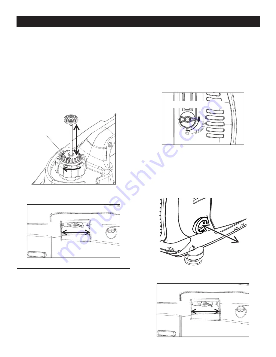
7. Carefully adjust the choke to approximately the ½ position
until the engine begins to run smoothly, then push the lever all
the way to the left (Figure 6).
8. Make sure the bottom of the generator is not blocked by sand,
leaves, grass, etc. as the cooling vents are located on the
bottom of the unit.
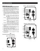
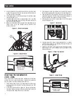
Figure 5 - Prime Fuel System
FUEL
SYSTEM
VENT
PLUNGER
VENT
Figure 6 - Adjust Choke
ENGINE CHOKE
OPERATION
ON
I
OFF
O
STARTING THE GENERATOR
(1600 - 2000)
Once the fuel and oil levels have been checked and it has been
verified there are no electrical devices connected, the generator
may be started. Turn the EcoMode Switch OFF (O).
1. Open the fuel valve (Figure 7), located below the starter rope
pull, by turning to the valve 90° counter-clockwise to the “ON”
(I) position.
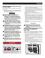
2. Locate the primer bulb (See Figure 8). Slowly, fully depress
the primer bulb and release. Allow the primer bulb to return to
its original state. Repeat this six (6) more times.
3. If the engine is cold or has not been run for some time, engage
the choke by pushing the choke lever to the right (Figure 9).
4. Grip the handle for the pull starter and brace your other hand
against the generator. Pull the rope slowly until resistance is
felt, then pull the rope rapidly up to three (3) times.
5. If the engine does not start, repeat steps 2-4 until the engine
fires and begins to run.
Figure 7 - Fuel Valve
TURNING THE FUEL ON
6. Carefully adjust the choke to approximately the ½ position
until the engine begins to run smoothly, then push the lever all
the way to the left (Figure 9).
7. Make sure the bottom of the generator is not blocked by sand,
leaves, grass, etc. as the cooling vents are located on the
bottom of the unit.
Figure 8 - Prime Fuel System
Figure 9 - Adjust Choke
ENGINE CHOKE
OPERATION
ON
I
OFF
O
Operation
Summary of Contents for G0060651
Page 19: ...17 Notes ...
Page 20: ...Manual Part No 0J9692 Revision B 02 25 13 ...
Page 39: ...37 Notas ...
Page 40: ...N º de parte del Manual 0J9692 Revisión B 02 25 13 ...
Page 59: ...57 Remarques ...
Page 60: ...N de pièce manuelle 0J9692 Révision B 25 02 13 ...

