background image


7

E

STABLISHING 

C

OMMUNICATION 


Between the Scanner and the Access Point Device 

To establish communication between the scanner and access point device: 
 
1.  Connect the access point device to the host system (

see pages 5 - 6

). 

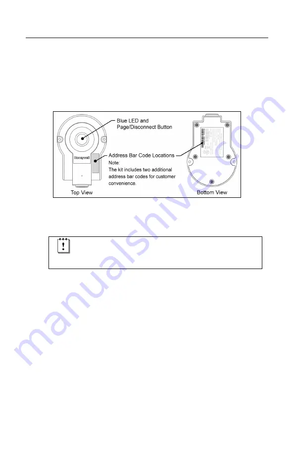
2.  Scan the address bar code on the access point device to establish a 
 

communication connection between the scanner and the access point 


device.   


Figure 10.  Address Bar Code


3. 

If successful, the scanner will respond with two beeps and the LED's on 


both the scanner and access point device will stop flashing. 


Important Note:  
The communication link between the scanner and the 
access point device is determined by the last address 
code scanned.  

Summary of Contents for FocusBT AP-010-BT

Page 1: ...AP 010 BT and AP 100 BT Access Point Device with Bluetooth Wireless Technology Installation Guide ...

Page 2: ...rior written consent except by reviewer who may quote brief passages in a review or provided for in the Copyright Act of 1976 Trademarks Metrologic is a registered trademark of Metrologic Instruments Inc Products identified in this document are hereby acknowledged as trademarks registered or otherwise of Metrologic Instruments Inc or their respective companies ...

Page 3: ...st Connections 5 USB Host Connections 6 Keyboard Wedge Host Connections 6 RS485 Host Connections 6 Establishing Communication Between the Scanner and the Access Point Device 7 Access Point Device Operation Page Disconnect Button 8 Visual Indicators 8 Configuration Procedures Metro Protocol Compatibility 9 CodeXML Protocol Compatibility 10 Access Point Device Configuration in CodeXML Mode 11 Option...

Page 4: ...rading the Firmware 17 Upgrading the Firmware in the Access Point Device 17 Upgrading FocusBT Firmware via the Access Point Device 18 Design Specifications 19 Device and Cable Terminations Device Pinout 20 Cable Pinout Connections 21 Regulatory Compliance EMC 23 Limited Warranty 25 Index 26 Contact Information and Office Locations 27 ...

Page 5: ...ACE SUPPORT Interfaces supported include AP 010 BT OR AP 100 BT RS232 RS485S USB Keyboard Wedge S Applicable for IBM Host applications Base Kit Components and Optional Accessories BASIC KIT Part Description AP 010 BT OR AP 100 BT Access Point Device Class 2 radio 10 m OR Access Point Device Class 1 radio 100 m 70 79035 Access Point Device with Bluetooth Wireless Technology Installation Guide Avail...

Page 6: ...7 3 AUX Cable Black S Applicable for IBM host applications Other items may be ordered for the specific protocol being used To order additional items contact the dealer distributor or call Metrologic s Customer Service Department at 1 800 ID METRO or 1 800 436 3876 Components ITEM NO DESCRIPTION LOCATION 1 Page Disconnect Button Blue LED see page 8 2 Mounting Holes Qty 2 3 10 Pin RJ45 Female Socket...

Page 7: ...ure 2 Mounting Specifications Cable Removal Turn off power to the host system before removing the cable from the access point device If the cable is a PowerLink cable disconnect the power supply on the cable Figure 3 Cable Removal 1 Locate the small pinhole on the top of the access point device see figure above 2 Bend an ordinary paperclip into the shape shown above 3 Insert the paperclip into the...

Page 8: ...es examples of the labels and their locations on the access point device Figure 4 Label Location with Examples Caution To maintain compliance with applicable standards all circuits connected to the scanner must meet the requirements for SELV Safety Extra Low Voltage according to EN IEC 60950 1 To maintain compliance with standard CSA C22 2 No 60950 1 UL 60950 1 and norm EN IEC 60950 1 the power so...

Page 9: ...e host connections applicable to the interface type Figure 5 Cable Installation RS232 Host Connections 1 Turn off power to the host system 2 Connect the female 9 Pin D type connector to a dedicated RS232 communication port on the host system 3 Plug the external power supply into the power jack on the PowerLink cable Check the AC input requirements of the power supply verify the voltage matches the...

Page 10: ...plied with the device for proper connections 4 Turn on power to the host system RS485S Host Connections 1 Turn off power to the host system 2 Connect the SDL connector into a dedicated Port 9 on the host system 3 Plug the external power supply into the power jack on the PowerLink cable Check the AC input requirements of the power supply verify the voltage matches the AC outlet The outlet must be l...

Page 11: ...e address bar code on the access point device to establish a communication connection between the scanner and the access point device Figure 10 Address Bar Code 3 If successful the scanner will respond with two beeps and the LED s on both the scanner and access point device will stop flashing Important Note The communication link between the scanner and the access point device is determined by the...

Page 12: ...unication 1 Press and hold down the button on the access point device for more than 3 seconds The blue LED on the access point device will start to flash indicating there is no communication link established To re establish communication 1 Scan the address bar code on access point device with the scanner Visual Indicators The page disconnect button is also the blue LED status indicator see figure ...

Page 13: ... is established between the scanner and the access point device Scanned data and custom configuration settings will be lost if a communication link is not established between the scanner and the access point Scanner configuration changes can be done either by scanning configuration bar codes in the MetroSelect Single Line Configuration Guide MLPN 00 02544x or with the MetroSet2 program version 3 2...

Page 14: ...igure a scanner in the CodeXML protocol mode via the access point device are outlined on page 11 CodeXML Firmware Requirements Scanner Model Firmware Version Focus BT 15701 or higher To configure a scanner to use the CodeXML protocol 1 Scan the Disable Metrologic Protocol bar code Disable Metro Protocol 1 2 5 6 0 4 2 Scan the Recall Defaults bar code Recall Defaults 9 9 9 9 9 8 3 Scan the Enable C...

Page 15: ... the Enable Metro Protocol bar code Enable Metro Protocol 1 2 5 6 1 4 4 Scan all configuration bar codes required for the custom configuration i e keyboard type country keyboard type suffix or prefix settings Country keyboard bar codes are located on page 14 Additional configuration bar codes can be found in the MetroSelect Single Line Configuration Guide PN 00 02544x and the Area Imaging Suppleme...

Page 16: ...1 6 6 1 3 The scanner transmits a carriage return after each bar code Disable Line Feed Suffix 1 1 6 6 0 2 Enable Line Feed Suffix 1 1 6 6 1 2 The scanner transmits a line feed after each bar code Disabled when keyboard wedge defaults are loaded Disable CodeXML New Line Suffix 1 2 5 6 0 6 Enable CodeXML New Line Suffix 1 2 5 6 1 6 Disable Protocol Disable CodeXML Protocol 1 2 5 6 0 7 Disable Metro...

Page 17: ...nd Bluetooth Software Version 9 9 8 0 4 4 Send Address 9 9 8 0 4 5 Communications Load RS232 Defaults 9 9 9 9 9 2 Load Keyboard Wedge Defaults 9 9 9 9 9 4 Load USB IBM OEM Defaults 9 9 9 9 7 0 Load RS485 Defaults 9 9 9 9 5 2 LED Enable LED 1 1 8 3 1 0 Disable LED 1 1 8 3 0 0 Enable LED Flash when Disconnected 1 2 3 7 1 2 Disable LED Flash when Disconnected 1 2 3 7 0 2 Bright LED 1 2 3 9 0 6 Dim LE...

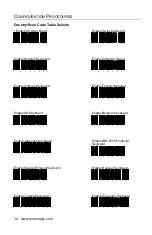
Page 18: ...yboard 4 1 6 2 4 0 Enable German Keyboard 4 1 6 2 3 0 Enable French Keyboard 4 1 6 2 2 0 Enable UK Keyboard 4 1 6 2 1 0 Enable Belgium Keyboard 4 1 6 2 0 0 Enable Japanese Keyboard 4 1 6 2 1 0 0 Enable IBM 4700 Financial Keyboard 4 1 6 2 7 0 Enable Sweden Finland Keyboard 4 1 6 2 9 0 Enable Russian Keyboard 4 1 6 2 1 3 0 Enable Turkish Keyboard 4 1 6 2 1 2 0 Enable Slovenian Keyboard 4 1 6 2 1 1 0...

Page 19: ... A communications window will open displaying the progress of the upload A message will appear in the window when the upgrade is complete 7 Click on the Tools menu at the top of the screen 8 Select View Current Settings from the drop down list 9 The Scanner Settings window will open listing the custom settings uploaded from the access point device Default settings will not be listed see example in...

Page 20: ...rted scanner list 4 Choose Focus BT with Access Point from the list 5 Select an interface i e RS232 Keyboard Wedge USB then click OK 6 Select and modify the configuration options in the Scanner Functions Menu 7 Choose Save As from the File menu to save the configuration 8 Click on the Down button 9 A communications window will open displaying the progress of the download The unit will beep and a m...

Page 21: ...system 2 Start the MetroSet2 software 3 Click on the plus sign next to POS Scanners to expand the supported scanner list 4 Choose the Focus BT with Access Point from the list 5 Click on the Configure Focus BT with Access Point Scanner button 6 Select the interface from the Prompt Window 7 Choose AP NEC or AP Silabs from the options list located on the left side of the screen to upgrade firmware in...

Page 22: ...re 3 Click on the plus sign next to POS Scanners to expand the supported scanner list 4 Choose the Focus BT with Access Point from the list 5 Click on the Configure Focus BT with Access Point Scanner button 6 Select the interface from the Prompt Window 7 Choose FocusBT from the options list located on the left side of the screen to upgrade FocusBT firmware 8 Click on the Select File button in the ...

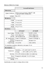
Page 23: ... W Maximum 0 85 W Maximum Current 160 mA Maximum 170 mA Maximum DC Transformers Class II 5 2VDC 1A Class II 5 2VDC 1A Wireless Technology Bluetooth V2 0 Bluetooth V2 0 Radio Range 10 m 33 ft 100 m 328 ft For regulatory compliance information see pages 23 24 ENVIRONMENTAL Operating 0 C to 40 C 32 F to 104 F Temperature Storage 20 C to 60 C 4 F to 140 F Humidity 5 to 95 relative humidity non condens...

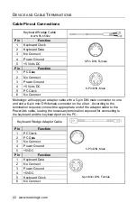
Page 24: ...10 Shield Ground USB Keyboard Wedge 10 Pin RJ45 10 Pin RJ45 Pin Function Pin Function 1 Ground 1 Ground 2 Tied to Pin4 in Cable 2 Tied to Pin3 in Cable 3 Reserved 3 Tied to Pin2 in Cable 4 Tied to Pin2 in Cable 4 PC Data 5 Reserved 5 PC Clock 6 USB D 6 KB Clock 7 Tied to Pin9 in Cable 7 Reserved 8 USB D 8 KB Data 9 PC 5VDC 9 PC 5VDC 10 Shield Ground 10 Shield Ground RS485S 10 Pin RJ45 Pin Function...

Page 25: ... CTS 3 RXD 4 Reserved 5 Reserved 6 RTS 7 Reserved 8 TXD 9 5VDC 9 Pin D Type Connector USB Communication Cable MLPN 55 55535 Pin Function 1 PC 5V V_USB 2 D 3 D 4 Ground Shield Shield Non Locking Type A RS485S Cable MLPN 55 55512 Pin Function 1 Ground 2 IBM A 3 IBM B 4 Reserved SDL A Key S Applicable for IBM Host applications ...

Page 26: ...apter cable with a 5 pin DIN male connector on one end and a 6 pin mini DIN female connector on the other According to the termination required connect the appropriate end of the adapter cable to the PowerLink cable leaving the necessary termination exposed for connecting to the keyboard and the keyboard port on the PC Keyboard Wedge Adapter Cable Pin Function 1 PC Clock 2 PC Data 3 No Connect 4 P...

Page 27: ...ference in which case the user will be required to correct the interference at their own expense Any unauthorized changes or modifications to this equipment could void the user s authority to operate this device This device complies with part 15 of the FCC Rules Operation is subject to the following two conditions 1 This device may not cause harmful interference and 2 this device must accept any i...

Page 28: ... or television reception which can be determined by turning the equipment off and on the user is encouraged to try to correct the interference by one or more of the following measures Reorient or relocate the receiving antenna Increase the separation between the equipment and receiver Connect the equipment into an outlet on a circuit different from that to which the receiver is connected Consult t...

Page 29: ... to use or misuse produced from integration of the Product into any mechanical electrical or computer system The warranty is void if i the case of the Product is opened by anyone other than Metrologic s repair department or authorized repair centers or ii any software is installed on the Product other than a software program approved by Metrologic THIS LIMITED WARRANTY EXCEPT AS TO TITLE IS IN LIE...

Page 30: ...stomer Service 2 25 D DC see power E EMC 23 Emissions 23 F Firmware 17 18 I Immunity 23 Indicator 19 Visual 2 Interface 19 Keyboard Wedge 1 2 6 22 RS232 1 2 5 21 RS485 1 2 6 21 USB 1 2 21 K Keyboard Wedge see Interface L Labels 4 LED see indicator M Manual 2 Mounting hole 2 P Page Disconnect Button 2 Power 2 5 R RMA 25 RS232 see Interface RS485 see Interface T terminations 21 22 transformer see po...

Page 31: ......

Page 32: ...70 79035A October 2008 Printed in China 2008 Honeywell International Inc ...

Reviews: