background image

EXCEL 10 W7751H SMART VAV ACTUATOR

95-7553—04

2

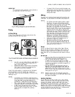
Fig. 2. W7751H mounting dimensions in in. (mm).

The W7751H assembly is field mounted to the VAV box 

damper shaft, the same as used for a typical actuator. The 

actuator on the W7751H opens or closes a damper by driving 

the damper shaft in either the counterclockwise (CCW) or 

clockwise (CW) direction. The actuator has a mounting tab on 

the bottom for securing to a VAV box damper. The mounting 

tab is accessible through a hole in the controller with its cover 

removed (see Fig. 3). The tab is sized for a 1/4 in. (6 mm) 

screw or pin (not included).

The controller enclosure on the W7751H is constructed of a 

sheet metal housing and a plastic snap-on cover. Controller 

wiring on the W7751H is terminated to screw terminal blocks 

located under the snap-on cover. See Wiring section. The 

sheet metal housing has two 1/2 inch (13 mm) knockouts (see 

Fig. 2) compatible with 1/2 inch (13 mm) or 3/4 inch (19 mm) 

conduit.

NOTE: The assembly is intended only for mounting to a 

horizontal shaft.

The W7751H actuator is shipped in the fully clockwise (CW) 

position (90 degree). The W7751H Assembly must be 

mounted to a horizontal damper shaft to assure proper heat 

dissipation from the controller housing. Mount the W7751H so 

that the actuator is parallel with the VAV box damper housing. 

In general, it is recommended that a washer or spacer be 

added between the VAV box damper housing and the actuator 

mounting tab to keep them parallel. See Fig. 4.

CAUTION

Equipment Damage Hazard.

Mounting actuator unevenly with damper housing 

can damage actuator.

Mount actuator flush with damper housing or add 

spacer between mounting tab and damper box 

housing. (See Fig. 4.)

M10523

CCW

CCW

CW

CW

60

45

45

60

5-7/8

(149)

1-13/16

(46)

1

(25)

3-5/8  (92)

4-1/16  (103)

1-13/16  (46)

1-5/16 (33)

MAINTAIN A 

MINIMUM DISTANCE 

OF 3 IN. (76 MM)

FROM OTHER 

DEVICES OR PANELS 

FOR REMOVING 

CONTROLLER COVER

3-3/4  (95)

MAINTAIN A MINIMUM DISTANCE

OF 4 IN (100 MM) FROM OTHER 

DEVICES OR PANELS FOR 

ATTACHING PNEUMATIC AIR 

FLOW TUBING

2-1/8

(54)

DE-CLUTCH

LEVER

DE-CLUTCH

LEVER

3-3/4

(95)

1-15/16  (49)

3/4

(19)

3/4

(19)

Summary of Contents for Excel 10 W7751H

Page 1: ...riac output loads must draw a minimum current of 25 mA at 24 Vac 60 Hz nominal Triac maximum current rating 77 mA The actuator on the W7751H mounts directly onto the VAV box damper shaft and has up to 70 lb in torque 8 Nm 90 degree stroke and 90 second timing at 60 Hz The actuator on the W7751H can accommodate the optional field installed auxiliary switches NOTE Mounting thermostat sensor greater ...

Page 2: ...duit NOTE The assembly is intended only for mounting to a horizontal shaft The W7751H actuator is shipped in the fully clockwise CW position 90 degree The W7751H Assembly must be mounted to a horizontal damper shaft to assure proper heat dissipation from the controller housing Mount the W7751H so that the actuator is parallel with the VAV box damper housing In general it is recommended that a wash...

Page 3: ...damper opening angle 45 60 or 90 degrees Fig 5 Determining rotation direction CW or CCW for damper opening If damper shaft diameter is 3 8 inch 10 mm round or square use part 201391 Shaft Adapter shipped with the W7751H Smart VAV Actuator Ensure it is placed opposite set screws See Fig 6 The adapter centers a 3 8 in 10 mm shaft in the hub Failure to use the adapter on a 3 8 in 10 mm shaft causes t...

Page 4: ... yet Before the part no 201614 Range Stop Pin which is shipped with the W7751H Smart VAV Actuator can be inserted in either the 45 or 60 degree CW slot the damper actuator must be driven fully open CCW To do this the controller on the W7751H must be wired powered and connected to the portable PC via the Serial LonTalk Adapter SLTA The SLTA connects to the controller on the W7751H via the jack for ...

Page 5: ...a verified earth ground for each controller in the group See Fig 10 Controller configurations are not necessarily limited to three devices but the total power draw including accessories cannot exceed 100 VA when powered by the same transformer See System Engineering form 74 2949 for power wiring recommendations All loads on an Excel 10 Controller must be powered by a single transformer Keep the ea...

Page 6: ...he portable PC via the SLTA The SLTA connects to the controller on the W7751H via Network Access Jack on the T7770 Wall Module or by B Port on the Q7750A Zone Manager From E Vision Software drive the W7751H actuator and halt the motion at the desired position for switch operation NOTE When installed angular position indicator on the switch face moves from 90 to 0 degrees during CCW motion and from...

Page 7: ...air solid conductor wire For nonplenum areas use CMP listed cable In plenum areas use CMP listed cable Do not bundle output wires with sensor digital input or LONWORKS Bus wires Ensure that neither LONWORKS Bus wire is grounded In noisy high EMI environments avoid wire runs parallel to noisy power cables motor control centers or lines containing lighting dimmer switches Keep at least 3 in 76 mm of...

Page 8: ...T BE TWISTED TOGETHER BEFORE INSERTING INTO THE TERMINAL BLOCK MICROBRIDGE DP SENSOR AIR FLOW DP PICKUP AIR FLOW DIRECTION LOW HI 2 M6410 SERIES 60 VALVE ACTUATOR COM STEM UP STEM DOWN TRIAC EQUIVALENT CIRCUIT TWO OR THREE WAY VALVE SET PT 1 2 3 4 5 6 7 8 9 10 11 12 EARTH GROUND 24 VAC COM OUT 1 OUT 2 E BUS COMM OUT COMM IN 24 VAC NOTE LOAD POWER WIRE IS CONNECTED TO TERMINAL 1 W7751H M10526 1 2 2...

Page 9: ... the Excel 10 FTT Termination Module Installation Instructions form 95 7554 Correct placement of the termination module s is required for proper LONWORKS Bus communications Step 2 Startup Broadcasting the Service Message The Service Message allows a device on the LONWORKS Bus to be positively identified The Service Message contains the controller neuron ID number and therefore can be used to confi...

Page 10: ...appears in one of the following allowable states 1 Off no power to the processor 2 Continuous on processor is in initialized state 3 Slow blink controlling normal state 4 Fast blink when the Excel 10 VAV Controller has an alarm condition When an Excel 10 has an alarm condition it reports it to the central node on the LONWORKS Bus Also the Excel 10 VAV Controller variables AlarmLogX where X is 1 th...

Page 11: ... BLOCK ML7984B REHEAT VALVE ACTUATOR PWM OUTPUT FROM CNTRL PWM H 24 VAC PWM VALVE ACTUATOR 24 N 24 H T6 T5 C B W R SERIES OR PARALLEL FAN CONTACTOR 24 VAC SET PT 1 2 3 4 5 6 7 8 9 10 11 12 24 VAC COM OUT 1 OUT 2 E BUS 24 VAC W7751H M10530 WALL MODULE EARTH GND SENSOR BYPASS LED NOT EARTH GROUND TRIAC EQUIVALENT CIRCUIT 3 2 4 1 1 2 3 4 REVERSE WIRES INCREASE DECREASE TO REVERSE ACTION DIRECT REVERS...

Page 12: ... only if used for Energy Management Q7740A B and Q7751A Devices for use on an Energy Management and or Smoke Control 14507287 Series Power Supplies W7751B2010 W7751D2016 W7751F2011 W7751H2025 Series 9 W7761A2010 Q7750 Q9200 XFL521 XFL522 XFL523 XFL524 XL500 XLINK Connect the controller with the laptop PC To do this the controller on the W7751H must be wired powered and connected to the portable PC...

Reviews: