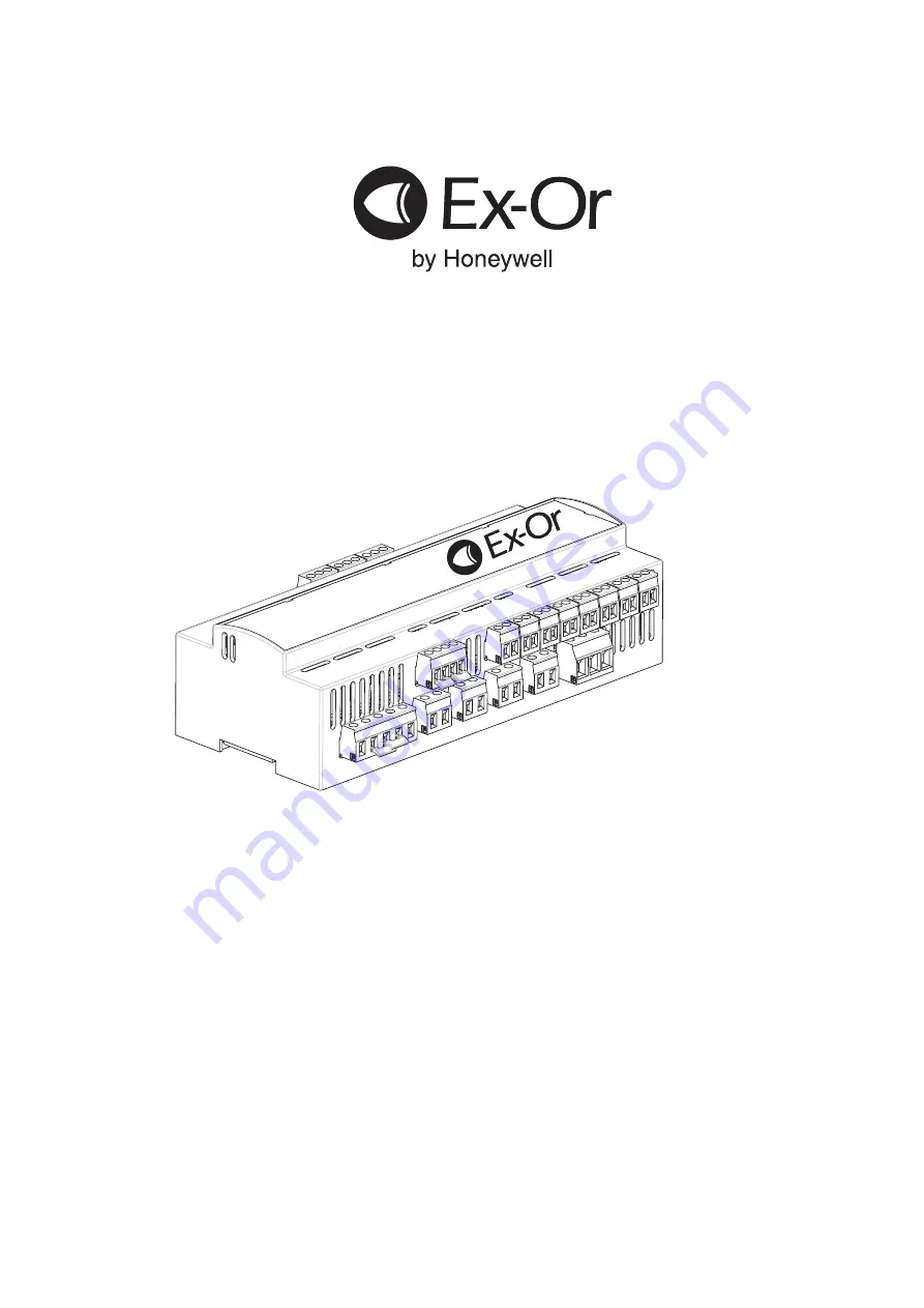
CDH4U5
4-Channel Programmable
Intelligent Lighting Control Module
Installation and Commissioning Instructions
Page 1: ...CDH4U5 4 Channel Programmable Intelligent Lighting Control Module Installation and Commissioning Instructions ...
Page 2: ...uct simplifies installation whilst providing an intelligent lighting control system Provision is made for 4 volt free power outputs rated for 415V isolation Additionally the unit features a switched output for Maintained Live to allow initiation of Emergency Lighting Test The CDH4U5 has the ability to operate from dual supplies with the capability to modify its operating behaviour when failure is ...
Page 3: ...wn in the diagram one or more channels may be powered from either of the supplies Ballast N L E D D Ballast N L E D D Ballast Ballast Ballast N N N L L L E E E D D D D D D 1 DETECTOR PORTS 2 3 4 5 B COM A B COM A B COM A B COM A B COM A 1 2 3 4 5 SELV SWITCH INPUTS VOLT FREE CHANNELS 1 1 2 2 COMMS BUS 4 3 2 1 DIMMING CHANNELS N L MAINS INPUT VOLT FREE CHANNELS N2 L2 N1 L1 CH2 ML CH3 CH1 CH4 D D CH...
Page 4: ... the unit an external change over contactor is required Line terminals from each of the supplies N1 L1 and N2 L2 are connected via the change over contactor The Live and Neutral outputs from the contactor are connected to the mains input of the unit In the case of failure of one of the supplies the change over contactor switches to the alternative supply to ensure continuous supply to the unit As ...
Page 5: ...k comprising a common and two returns from normally open contacts Four plugs are provided with each CDH4U5 additional plugs can be ordered using the code CDHIP 5 pieces per pack Note that if the SELV status of any one of the switches is compromised by reason of inadequate insulation or segregation of the cabling then the SELV status of all other switchesAND OF THE DETECTORS will also be compromise...
Page 6: ...ns 6 PARAMETERS OPTIONS Per Box Parameters Switch A 1 5 Switch B 1 5 Switch 6A 6B 7A 7B User may choose any option for Switch A or Switch B from following Sustain Brighten Dim Off Scene 01 06 On Partition OneSwitch On Dim Off Brighten On Brighten Off Dim Emergency Test Emergency End See separate table for detailed description of Switch Input options Detector 1 5 Range Max 100 Max 75 Max 50 High 10...
Page 7: ...r example 20 Ballasts Maintained live output 6A Mains supply terminal capacity 2x2 5mm or 1x4mm Override switch input connector 2 5mm MLS bus connector 2 5mm MLS bus cable 1 5mm unscreened twisted pair seeApplication NoteAN4001 Case material Self extinguishing blend PC ABS Case finish Gray RAL7035 IPrating 20 Dimensions 9 m 1m 62mm 3m 21 m Volt free Channels Volt free Channels Dimming Channels Com...
Page 8: ... Power Supply Unit Wireless switch enabled DSI Dimming CDH4U5 RBDALIWL 4 Channel LCM with MLS Bus Power Supply Unit Wireless switch enabled DALI Dimming Plug in Cards CDHDC Plug in Digital Dimming Card CDHAC Plug in Analogue Dimming Card CDHBC Plug in MLS Bus Interface CDHRB Plug in MLS Bus Power Supply Unit CDHWL Plug in Wireless EnOcean Card Presence Detectors with photocell MLS2500CDR Corner mo...