


Controller Information
Part No.: 44200004 - Revision 2
SVP Controller Operation Manual
2-13
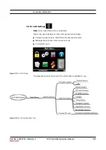
Entity
Description
Sensor used as
“high sensor”
Sensor used as
“low sensor”
[Total]
Selects the Upstream Sensor to be
used as the “high” volume gate and the
Downstream Sensor to be used as the
“low” volume gate. This is the default
configuration
Upstream Sensor
Downstream Sensor
[Upstream]
Selects the Upstream Sensor to be
used as the “high” volume gate and the
Midstream Sensor to be used as the
“low” volume gate
Upstream Sensor
Midstream Sensor
[Downstream]
Selects the Midstream Sensor to be
used as the “high” volume gate and the
Downstream Sensor to be used as the
“low” volume gate
Midstream Sensor
Downstream Sensor
2.3.6.3 I/O Settings
2.3.6.3.1 Alarm Relay Output
The Alarm Relay Output can be configured to be Energized (normally
closed) or De-energized (normally open).
2.3.6.4 Alarms
The following alarm entity applies to Service Due Reminder and Machine Fault.
Entity
Description
Value range
[Alarm action]
With this entity the user can configure the
alarm behavior in case this particular alarm
will occur
•
<Disabled>
: The alarm is ignored
•
<Display>
:
- Alarm shown on the display
- Alarm-indication output set to ON
- Next prover cycle will be allowed
•
<Shutdown>
:
- Alarm shown on the display
- Alarm-indication output set to ON
- Operation of further machine run cycles
are disabled until the alarm is cleared
- Still able to perform diagnostics via
RunProver Test or via Dashboard screen
from LAD
The Service Due Reminder alarm is activated when the cycle count
reaches the threshold value programmed by the user at the Cycle Count
Threshold menu. The default setting for the Cycle Count Threshold
is 1000.