background image

EchoView User’s Guide 


10 


3.1.


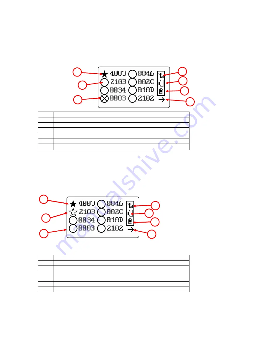
LCD Display (Monitoring) 


LCD Display (Monitoring)


Selected monitor (solid circle or star)* 

Unselected monitor (open circle or star) 

Offline monitor (open circle with “X”) 

Radio transmission indicator (“H” is shown for “Host”) 

Audible alarm on/off indicator (“on” shown) 

Battery indicator 

Arrow indicating more than 8 instruments, pointing to next “page” 

 
Note:

 The Unit ID is typically the radio ID, depending on the portable monitor’s setting. 


3.2.


LCD Display (In Alarm) 


Monitor in alarm and selected (solid star) 

Unselected monitor in alarm (open star) 

Unselected monitor not in alarm (open circle) 

Radio transmission indicator (“H” is shown for “Host”) 

Audible alarm on/off indicator (“on” shown) 

Battery indicator 

Arrow indicating more than 8 instruments, pointing to next “page” 


3


3


Summary of Contents for EchoView

Page 1: ...EchoView User s Guide 1 EchoView User s Guide Rev F January 2019 P N F04 4001 000 ...

Page 2: ...r your product online by visiting https www honeywellanalytics com en support product registration By registering your product you can Receive notification of product upgrades or enhancements Be alerted to training classes in your area Take advantage of special offers and promotions ...

Page 3: ... 7 1 2 LCD Contrast 19 7 1 3 Serial Number 19 7 1 4 Firmware Version 20 7 1 5 Factory Reset 20 7 1 6 Edit Password 21 7 1 7 Page Disable EchoView Host 22 7 1 8 Exit 23 7 2 Wireless 23 7 2 1 Ping Net 24 7 2 2 PAN ID Setup 24 7 2 3 Join Net 25 7 2 4 Channel Setup 26 7 2 5 Exit 27 8 Viewing Data From Connected Monitors 27 8 1 Viewing Alarm Data 28 8 2 One Monitor In Alarm 28 8 3 Multiple Monitors In ...

Page 4: ...Troubleshooting 37 11 Year Of Manufacture 38 12 Appendix A External Battery Replacement 39 12 1 External Battery Usage 40 12 2 External Battery Replacement Process 42 13 Appendix B Installation 43 13 1 Magnet Mount Installation 43 13 2 Fixed Installation 44 13 3 Magnetic Mount Alternative Installation 47 ...

Page 5: ...and how to set the correct parameters and interpret the obtained results CAUTION To reduce the risk of electric shock turn the power off before opening this instrument or performing service Never operate the instrument when the instrument is open Service this product only in an area known to be non hazardous WARNING Use only the Lithium battery or external rechargeable battery provided by Honeywel...

Page 6: ...the equipment This equipment has been tested and found to comply with the limits for a Class B digital device pursuant to part 15 of the FCC Rules These limits are designed to provide reasonable protection against harmful interference in a residential installation This equipment generates uses and can radiate radio frequency energy and if not installed and used in accordance with the instructions ...

Page 7: ... The EchoView wirelessly receives the data shown on an FMC2000 controller in a MeshGuard network and displays them on its screen and delivers audible and visible alerts The EchoView contains no sensors Its built in radio board operates on a frequency of 2 4GHz and complies with IEEE 802 15 4 standard It works with the FMC2000 wireless controller on a flexible robust wireless network to provide rel...

Page 8: ...twork forming and configuration Operating distance up to 300 m line of sight Very low cost installation no hardwiring involved Large area coverage with multi hop mesh network Field replaceable battery Loud audio alarm 90dB 30cm 12 Easy to read continuous display of signal strength Bright red flashing alarm Highly resistant to RFI interference IP 65 rated for outdoor use in harsh environments ...

Page 9: ... is available in a metal enclosure or a plastic enclosure Functionality is identical regardless of the enclosure 1 LED alarm 2 LCD with backlighting 3 Buzzer alarm 4 Battery cover on bottom 5 Y MODE and N keys 6 Antenna 6 1 2 3 5 4 Plastic Housing Metal Housing ...

Page 10: ...Arrow indicating more than 8 instruments pointing to next page Note The Unit ID is typically the radio ID depending on the portable monitor s setting 3 2 LCD Display In Alarm 1 Monitor in alarm and selected solid star 2 Unselected monitor in alarm open star 3 Unselected monitor not in alarm open circle 4 Radio transmission indicator H is shown for Host 5 Audible alarm on off indicator on shown 6 B...

Page 11: ...t to Mesh Router or up to 1km 0 6 miles User Interface Three keys Y MODE N Power Supply D size Lithium replaceable battery 3 6V Operation Time Internal Battery Up to 10 days External Battery Up to 45 days Operating Temperature 4 to 122 F 20 to 50 C Humidity 0 to 95 relative humidity non condensing Dimensions Metal Enclosure 15 7cm x 9 3cm x 5 1cm 6 2 x 3 7 x 2 0 Plastic Enclosure 26 5cm x 9 5cm x ...

Page 12: ...w Function Therefore you should perform this simple configuration before adding one or more EchoViews to a network To enable the Pager function on the FMC2000 Controller 1 Press the MENU key from Normal Operation Mode to enter the Configuration menu 2 Provide a 4 digit password the default value is 1234 3 Press Enter 4 The General Settings icon is highlighted Press Enter 5 Scroll to Advanced Setti...

Page 13: ...ED lights light up The display indicates that the unit is now on During startup the display shows the firmware version Next it shows the firmware s build date and time This is followed by the Unit Mode and Modem Type Note Modem type relates to its permanently set operating frequency For further information refer to page 23 ...

Page 14: ...re within the EchoView s range its display will only show the radio on indicator battery charge and buzzer on off icon If you see this screen check the following Is the antenna attached Does the Pan ID match the network you want to join Does the Channel match the channel on which the other instruments are operating Are the other instruments turned on and within range Did you change the Pan ID or C...

Page 15: ...ry alarm continues until the battery runs out Then the unit shuts down automatically Battery power is indicated with an icon in the lower right corner of the screen below the wireless communication indicator and buzzer icon Battery charge is shown from empty to full Note For a fixed system application an external power source the RAE PowerPak can be used as a substitute for the internal battery On...

Page 16: ...loying The EchoView When deploying a MeshGuard network that utilizes EchoViews make sure the rest of the network has been set up before using an EchoView The EchoView gets its information about the monitors on a network from the FMC2000 controller It does not aggregate network data from all its nodes Therefore make sure the FMC2000 is operational and in communication with all monitors on the netwo...

Page 17: ... see the following screen appear Press Y to enter the password If you make a mistake you can cycle through the digits by pressing MODE and then using Y and N to change the number in each position Note The default password is 0000 If your password is incorrect you see this screen After a few seconds the EchoView exits to its main screen When you have successfully entered Programming Mode you see th...

Page 18: ...te Two more screens contain additional options Note The scrolling wraps so once you reach the first or last item it starts scrolling through the items again Eight choices including Exit are available Buzzer On Off LCD Contrast Serial Number read only Firmware Version read only Factory Reset Edit Password Page Disable Exit To make a selection scroll until the circle to the left of your choice is bl...

Page 19: ...s menu To access it press MODE when its name is highlighted dark circle The contrast value is shown in the display Step through the digits from left to right by pressing MODE Change a digit s value by pressing Y to increase and N to decrease After the third digit you see a flashing Save your changes by pressing Y Exit without saving changes by pressing N Step back to the first digit by pressing MO...

Page 20: ...t make changes to the information To view it press MODE when its name is highlighted dark circle Press MODE to return to the Settings menu If you do not make a selection in 60 seconds it automatically exits to the menu 7 1 5 Factory Reset You can perform a factory reset to the instrument s original settings To access it press MODE when its name is highlighted dark circle You are asked whether you ...

Page 21: ...set changes all EchoView settings to factory default values These include PAN ID Channel IMPORTANT All custom configured settings are removed and cannot be retrieved 7 1 6 Edit Password You can change the password by selecting Edit Password At this screen input your new password over the old one or the default Increase the number from 0 through 9 by pressing Y Decrease the number from 9 through 0 ...

Page 22: ...t and a screen indicates that it has been successfully saved 7 1 7 Page Disable EchoView Host The Page feature can be enabled to allow up to four additional EchoView Host mimic panels to be used as part of a closed loop system When the Page feature is enabled the EchoView Host broadcasts instrument data These data can be picked up by mimic panels If no mimic panels are planned to be used this feat...

Page 23: ...less consists of editable parameters and actions to configure form and test a closed loop wireless network Under Programming Menu select Wireless Press Y to scroll up or N to scroll down through wireless sub menus Note When you reach the last item and continue scrolling a second screen appears The scrolling wraps so once you reach the first or last item of either screen it starts scrolling through...

Page 24: ...ng signal respond with a beep if they are within the range The Echoview does not beep or flash its LED lights You can also ping from an instrument in the network If it is within range the EchoView responds with a beep and an LED light flash If a network ping is unsuccessful check the following Is the antenna attached Does the PAN ID match the PAN ID of other instruments in the network Does the Cha...

Page 25: ...e programming Menu screen showing Settings Modem and Exit 7 2 3 Join Net This screen is for joining an existing network When you see this screen press MODE to form a network This function allows the radio to scan all available channels and choose the least congested one The screen now displays a message asking if you want to confirm your choice to join a network Press Y to join a network and autom...

Page 26: ...e the channel The range of available channels is shown in parentheses The screen also shows the channel number with the cursor blinking on the first digit Step from digit to digit from left to right by pressing MODE Change a digit s value by pressing Y to increase and N to decrease When you press MODE you see a flashing after the second digit Save your changes by pressing Y Exit without saving cha...

Page 27: ...he monitor is not in alarm To view the selected monitor s data select the monitor you want to view Scroll up or down the list by using the Y and N keys To make your selection press MODE The screen changes to show the data For example This provides you with an overview including The monitor s location if it has been programmed into the FMC2000 controller The type of monitor The type of sensor The a...

Page 28: ...ection Scroll until the circle to the left of your choice is black and then press MODE Note If you do not make a selection in 60 seconds it automatically exits to the main reading screen 8 2 One Monitor In Alarm Whenever a monitor on the network goes into alarm the EchoView also receives it and displays it When monitoring the network and when no alarms are present the EchoView s display looks like...

Page 29: ...e Only one monitor can be selected for viewing at a time When the icon of the monitor you want to view is highlighted then you can make your selection Press MODE The screen changes to show the data For example This provides you with an overview of the alarm state including The monitor s location if it has been programmed into the FMC2000 controller The type of monitor The type of sensor The type o...

Page 30: ...ored To view a monitor s peak reading 1 Press Y or N to scroll through the list of monitors Then press MODE to select the highlighted monitor The monitor s type and status are shown A Alarm R Real time Reading 2 Press N to advance through the sensor s information L Low Alarm H High Alarm 3 Hold the Y key for 3 seconds and the peak value is shown P Peak A Alarm Status To continue with readings pres...

Page 31: ... relays simultaneously 8 6 Enabling Disabling The Panic Button Function Note By default the Panic Button feature is disabled 1 Start the EchoView in Diagnostic mode by pressing and holding the Y and MODE keys simultaneously 2 Once startup is completed and the main screen is shown enter Programming mode by pressing and holding MODE and N simultaneously 3 Provide the 4 digit password and press Y to ...

Page 32: ... menu screen with Operating Mode selected Press N to advance to the screen with Exit highlighted Press MODE to exit to the main operating screen 8 7 Using The Panic Function The Panic function is designed so that it is very difficult to invoke by accident Start at the normal operating mode screen 1 From the normal operating mode screen press and hold all three buttons until you see this screen 2 N...

Page 33: ... to trigger press MODE This triggers only that one selected relay Note The relay on the FMC2000 controller remains triggered until it is cleared either at the FMC2000 or at the EchoView 8 7 3 Clear Relays Clear relays clears all of the relays on the controller even if only one relay was triggered Select Clear Relays and then press MODE to clear the relays After clearing the relays you can exit by ...

Page 34: ...tery Low Bat or Battery Low None None 8 7 5 Alarm Signal Summary Alarm Mode Buzzer LED EchoView low battery 1 beep per minute Monitor fault such as low battery sensor error etc 1 beep per second Monitor low alarm 2 beeps per second Monitor high alarm 3 beeps per second 8 8 Offline Monitor s If any other monitors on the network go offline the circle accompanying the monitor s name changes to a circ...

Page 35: ...EchoView User s Guide 35 9 Internal Battery Replacement Battery 3 pin end Hexagonal end Battery compartment Battery removal tool P N 019 2044 000 Battery cover Battery ...

Page 36: ... general waste 3 Insert the new battery with its positive pole towards the inside of the instrument 4 Replace the battery cover by turning it clockwise with the 3 pin end of the tool Note After changing the battery wait at least 60 seconds before turning the EchoView on WARNING Only change the internal battery in non hazardous locations and use the battery Honeywell RAE Systems provides P N 500 01...

Page 37: ...between the EchoViews on the network There is an obstruction between EchoViews Battery is low EchoViews have different PAN ID and or Channel numbers The distance should be around 300m 1 000 ft line of sight Relocate EchoViews or deploy MeshRouters to extend the range Relocate the EchoView or deploy one or more MeshRouters to extend the range Replace battery Set all units to the same PAN ID and Cha...

Page 38: ...ufacture refer to the serial number of the instrument The letter in the serial number indicates the year of manufacture For example M indicates the manufacturing year is 2010 Letter Year V 2018 W 2019 A 2020 B 2021 C 2022 D 2023 E 2024 F 2025 G 2026 H 2027 I 2028 J 2029 K 2030 ...

Page 39: ...ernal Battery Replacement 3 pin end Hexagonal end Adapter Maintenance tool P N 019 2044 000 Note For clarity EchoView s optional stainless steel enclosure is not shown Warning Only remove the external battery adapter in non hazardous locations ...

Page 40: ...ew in its steel enclosure are shown in the procedure below 1 Remove battery cover with the 3 pin end of the sensor and battery removal tool by turning counterclockwise 2 Lift off the cover 3 Insert the power end of the cable connected to the Power Pak 4 Use the open hex end of the wrench and with both pins mated with the two holes on the power end tighten by turning clockwise until it is snug Do n...

Page 41: ... mounting plate that holds both the EchoView and the RAE PowerPak Front side and rear views of the steel enclosure show how the EchoView is secured for mounting With the EchoView securely in its housing you can remove the cover over the battery compartment so that you can place the connector from the RAE PowerPak into the EchoView Use the maintenance tool as shown Maintenance tool P N 019 2044 000...

Page 42: ...rocess External battery replacement 1 Unplug the battery connector 2 Loosen the safety screw holding the battery 3 Mount a new battery on the mounting bracket 4 Tighten the safety screw 5 Connect the EchoView to the battery 6 Switch on the EchoView RAE PowerPak ...

Page 43: ...housing models uses a specially designed stainless steel enclosure that is permanently mounted It protects the plastic body EchoView from damage in industrial settings 13 1 Magnet Mount Installation This magnet is powerful enough to support the EchoView when it is placed against a flat steel or iron surface Important Keep the magnet away from computer hard drives The strong magnet can corrupt or e...

Page 44: ...lation Four reinforced holes in the rear of the enclosure allow for a screw to pass through to the mounting brackets The enclosure can be mounted to a vertical or horizontal pole Side View Front View Mounting Holes Vertical pole Horizontal pole ...

Page 45: ...l pole Loosely assemble the clamp parts around the pole Note that the screws have nuts that fit into the clamp parts The clamp parts are designed to hole the nut so that you do not need to use a wrench Hand tighten the parts until snug Tighten the hex screws from the front of the enclosure Once the clamp parts and the enclosure are securely held against the pole stop tightening Note The pole must ...

Page 46: ...over of the enclosure 4 Insert the hex screw into the cover s locking portion and tighten it 5 The EchoView is now ready to use Note The sensor cover on the bottom of the enclosure can be removed so that the filter and sensor can be inspected without removing the EchoView from the enclosure Simply pull off the cover and follow the maintenance procedures in this guide 1 2 5 4 3 ...

Page 47: ...closure instead of the clamps This approach provides the protection of the enclosure with the ease of installation afforded by the magnetic mounting 1 Insert screw through magnetic disc 2 Place the magnetic disc over the bottom hole on the rear of the enclosure 3 Tighten the screw until the disc is snug Side View Rear View ...

Page 48: ...Honeywell Internal For more information www raesystems com F04 4001 000 Rev A January 2019 2019 Honeywell International ...

Reviews: