background image

18

6.6 How to Bind BDR91T to ST9520C

NOTES:

• 

It is only possible to bind a BDR91T if both sensors (DT92E) have already been bound to the sensor slots in ST9520C.

• 

BDR91T can be bound as a CONTROL device, to operate a zone valve for example (refer to Honeywell for supported applications) or as a 

BOILER control (refer to Binding Table in section 6.2 for details).

a.

  Ensure the ST9520C slider is in the 

RUN

 position, then press and hold    ,   and Zone 2 

MODE

 buttons for 8 seconds to access the Guided 

Binding Menu. The message 

‘BIND MENU’

 will show briefly, followed by the binding display.

b.

  Refer to the table in Section 

6.3

 to determine whether you require to cancel any binding. The SENSOR binding slot will be displayed first. Use 

the     and   buttons to navigate to the CONTROL or BOILER binding slots, where 

‘CONTROL’

 or

 ‘BOILER’

 will appear on the display. If the 

display shows dashes it means there is nothing already bound in the slot. If the display shows

 ‘bnd’ 

it means there is something already bound.

c.

  Any existing binding can be cancelled by holding the   button for 8 seconds and the 

LoT™ Display

 will say 

‘RESET’

 for a few seconds.

d.

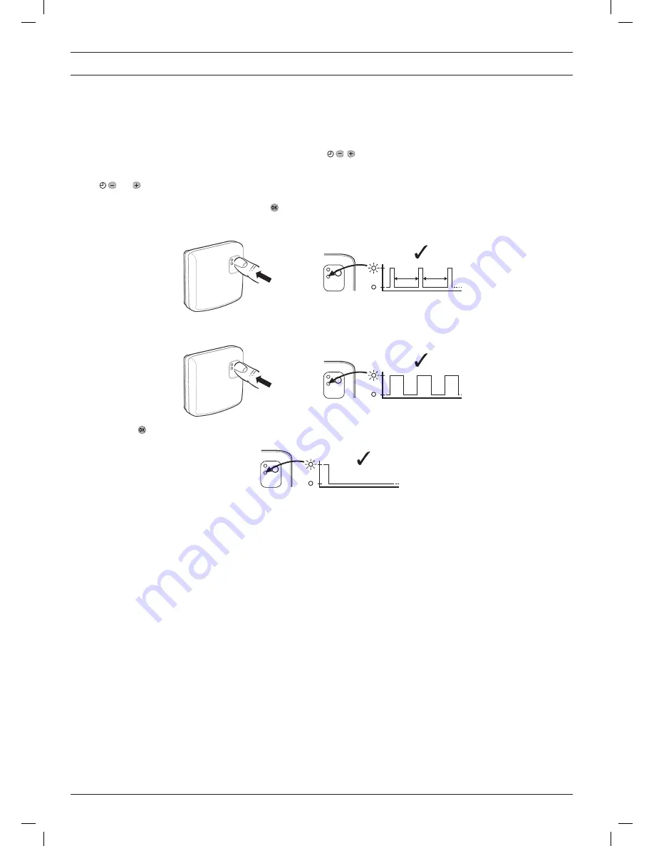
  Now go to the BDR91T. If you need to cancel any previous binding in BDR91T, hold the button down for 15 seconds. The red light will give a 

quick flash every second. Otherwise go to step 

e

.

e.

  Hold the BDR91T button for 5 seconds until the red light flashes on for 0.5s, off for 0.5s. The BDR91T is now in binding mode awaiting the binding 

message from ST9520C.

f.


Now press the   button on ST9520C to send the binding signal. If binding was successful the ST9520C display will stop flashing, ‘bnd’ will be 

shown, and the 

LoT™ Display

 will say 

‘COMPLETE’ 

for a few seconds. The flashing red light on BDR91T will also go off.

g.

  If binding was unsuccessful, repeat step f. if this fails, repeat steps

 d

. to 

f

. again. When binding has succeeded, proceed to step

 h

.

h.

  Exit Guided Binding Menu by moving the ST9520C slider to the next position and then back again to 

RUN

 (it will exit automatically after 10 

minutes if the slider is not moved).

i.


Now go to section 

6.7

 to verify communication by using the Signal Strength test.

15 s

0.1s

0.1s

0.1s

0.9s

0.9s

5 s

0.5s

0.5s

0.5s

0.5s

0.5s

Summary of Contents for DT92E

Page 1: ...stem Operation DT92E and ST9520C use 2 way communication on an 868MHz radio frequency RF band to control the heating system ST9520C operates as the control hub of the system and the DT92E thermostats are free to be positioned in suitable locations in the 2 separate heating zones This functionality is ideal for upgrading existing systems without a room thermostat to ensure compliance with Building ...

Page 2: ...s the building construction the diagram below illustrates an example of typical signal strength reduction Walls and ceilings reinforced with steel or plasterboard walls lined with metal foil reduce the RF signal significantly more RF Signal Propagation Installation Notes Installation Sequence Step by Step Typical example of Building Fabric Signal losses Signal Strength Wall Wall Wall Ceiling Max S...

Page 3: ...uirements c Surface mounting with surface wiring in mini trunking Clip the unit onto the hinges on the top of the wallplate and hinge down into position Tighten the two securing screws using a screwdriver Switch on the power the unit will now be operating according to the built in programme Note the ST9520C is supplied with a factory set clock for faster installation Refer to Y9520Z User Guide for...

Page 4: ...ves wired TPI boiler control 95 2 Wireless room thermostat wired valves OpenTherm 2 wire boiler control V4043H 2 PORT ZONE VALVE ZONE 2 B L U E G Y E L L O W B R O W N O R A N G E G R E Y V4043H 2 PORT ZONE VALVE ZONE 1 B L U E G Y E L L O W B R O W N O R A N G E G R E Y 3 AMPS MAX L N 230V 50 60Hz BOILER PUMP L N E ST9520C NOTE 2 N L 1 2 3 4 A B T1 L N E 1 2 3 4 5 6 7 8 9 10 V4043H 2 PORT ZONE VA...

Page 5: ...e of existing time controls but it is likely major wiring changes will be required for compatibility with the plumbing and controls changes Refer to the Honeywell Technical Help Desk for advice 1 8 Powering Up ST9520C 1 7 Replacing Other Time Controls 1 6 Wiring Diagrams cont Additional notes a Orange wires from zone valves are parked for convenience b Pump live is taken from boiler If pump is loc...

Page 6: ...l strength testing to ensure DT92E can be positioned in the best possible location To enter Signal Strength Test a Hold down the button for 2 seconds until the symbol is displayed b Hold down the and buttons together for 3 seconds until Inst appears in the display c Press the button Cont is now displayed d Hold the button for 3 seconds to enter Test mode e Signal Strength Test is entered from Test...

Page 7: ... to be separated from its mounting plate follow the simple steps shown below a For wall mounting install the mounting plate first then follow steps 1 2 and 3 to hinge the front piece on as shown in the diagrams b If the optional table stand is to be used first assemble the two pieces together as shown Next follow steps 1 2 and 3 to hinge the DT92E front piece onto its mounting plate and mount the ...

Page 8: ...positioned in a location where the RF signal strength from ST9520C is high The simplest way to identify such a location in advance is to use the signal strength feature on DT92E because DT92E can be moved around freely a Remove one DT92E from its mounting plate section 2 5 b Enter signal strength test section 2 3 c Identify a location close to the boiler where the signal strength is 3 or more d Af...

Page 9: ... changes that have been confirmed will be saved and used Note The Installer Modes and the Setup Menu will exit automatically after 10 minutes if the slider is not moved and no adjustments have been made in this time 4 SYSTEM CONFIGURATION ST9520C 4 1 ST9520C Installer Modes The ST9520C Programmer has a Service feature that can assist Social Housing Landlords to comply with the requirements of Regu...

Page 10: ... TEMP Minimum ON OFF time 13 MIN ON OFF 1 1 2 3 4 5 minutes Minimum ON OFF time SET MIN ON OFF Cycle rate 14 CYCLE RATE 6 3 6 9 12 Number of boiler cycles SET CYCLE RATE Proportional band width 15 PROP BAND 15 1 5 C 15 30 1 5 3 0 C Control proportional band SET PROP BAND Failsafe mode loss of RF communications 16 COMMS LOSS 0 0 1 0 off 1 on 20 HEAT OFF 20 PERCENT Reset all parameters 20 PROG RESET...

Page 11: ...ler the boiler may not allow low load operation Note When OpenTherm is enabled BOILER binding is not possible and anything already bound in the BOILER binding slot is deleted see page 16 Refer to Honeywell Technical Help Desk for wireless OpenTherm possibilities using the R8810A OpenTherm receiver ST9520C has the facility for a direct low voltage communications connection to the boiler using the O...

Page 12: ...RVICE PARAMETER Parameter ID LoT Display Description Default Value Range of Values Description LoT Display Description Enable or disable service alarm feature AL SERV MODE 0 0 1 0 disabled 1 enabled DISABLED ENABLED Number of days till next Service d SERV DAYS 364 001 to 400 001 400 000 service is overdue SET DAY COUNT Number of days for advance warning Ad DAYS NOTICE 28 0 to 28 0 28 SET DAYS NOTI...

Page 13: ...nge This allows you to enable or disable all the service alarm features At every step the LoT Display will inform you what the parameter means and what option you have selected The parameter ID is usually shown on the display separated by a colon from the parameter value f You can change the parameter value by pressing the or buttons At this point the description in the LoT Display will change and...

Page 14: ...ommences When the boiler service is overdue the screen will keep flashing the words SERVICE DUE every second If the NO ACTION option has been selected the unit will continue to operate as normal and the real time will continue to be shown If the SWITCH OFF or PROMPT Actions have been selected the SERVICE DUE message will flash and the word OFF will appear on the display The boiler has been switche...

Page 15: ...ange the value Confirm the change by pressing the button again to take you back to the parameter To Exit Installer Mode Hold the button for 3 seconds to exit Installer Mode Note The Installer Mode will exit automati cally after 10 minutes if no adjustments have been made in this time 5 SYSTEM CONFIGURATION DT92E 5 1 DT92E Installer Mode INSTALLER PARAMETER Parameter Default Value Range of Values D...

Page 16: ...efer to section 6 6 for sequence of steps Once a valid sensor is bound it is then possible to bind an output device such as a BDR91T relay box If this is to control remote zone valves for the heating zones then use the CONTROL binding slots In the special case of controlling a remote boiler use the special BOILER binding slot When this is bound the Guided Binding Menu then allows a signal strength...

Page 17: ...essage BINDING will be shown to indicate ST9520C is waiting for this message f Now bring DT92E or its front section minus mounting plate to approximately 1 metre from ST9520C g Put DT92E into binding mode as shown Press and hold the button for 2 seconds Hold the and buttons for 3 seconds until display shows Inst Press the button and the display shows Cont h If you do not need to cancel existing bi...

Page 18: ...c Any existing binding can be cancelled by holding the button for 8 seconds and the LoT Display will say RESET for a few seconds d Now go to the BDR91T If you need to cancel any previous binding in BDR91T hold the button down for 15 seconds The red light will give a quick flash every second Otherwise go to step e e Hold the BDR91T button for 5 seconds until the red light flashes on for 0 5s off fo...

Page 19: ...rs on the display c Press the button to activate the test The ST9520C will show SIGNAL TST and flash SS on the display d Go to the BDR91T where the red light will flash several times quickly in succession repeating every 5 seconds The number of flashes in each burst will be between 0 and 5 with 5 representing a strong signal and 0 a weak one e If the signal strength is less than 3 re position the ...

Page 20: ...plain the operation of the products to the User and help them to set their Zone 1 and Zone 2 programmes ST9520C has 3 built in profiles that can be used as a basis for typical User programmes 2 Explain when the User should contact someone to arrange a Service Visit and what you have programmed to happen when the Service is overdue 3 If required attach the self adhesive programme guide label to the...

Reviews: