background image

STRYKER CVAHU ZIO CONFIGURATION GUIDE


12 


Products Covered  

This System Engineering Guide describes how to 
configure Stryker CVAHU controller via TR71/75 
Zio wall module. 

Stryker CVAHU Controllers and related accessories 
to typical applications are as follows: 


Stryker CVAHU controller. 


TR71/75 wall modules. 


209541B FTT termination module. 


Organization of Manual 

This manual is divided into two basic parts: 
introduction and configuration. 

The Introduction provides information for Stryker 
LON configurable CVAHU controller and TR70 
series Zio/Zio Plus LCD wall modules, control 
application, control provided, product covered, and 
abbreviations. 

Configuration steps provide information for the 
engineering of Stryker LON configurable CVAHU 
controller by TR70 series Zio/Zio Plus LCD wall 
modules using its various function keys. 

The organization of the manual assumes a project 
is being engineered from installation to finish.  


Applicable Literature 

List of documents containing information related to 
the configurable lighting controllers as shown in 

Table 3


Table 3: List of applicable literature 


Form No.


Title


63-4529

—03 

Stryker

™ Lon Configurable 

VAV/CVAHU Controller 
Specification Data 

62-2029

—02 

Stryker

™ Lon Configurable 

VAV/CVAHU Controller 
Installation Instructions 

63-1322

—02 

Zio®/Zio Plus LCD Wall Modules 
Wall Module Specification Data 

62-0271-07 

Zio®/Zio Plus LCD Wall Modules 
Wall Module Installation 
Instructions 

63-2719 

LCD Wall Modules Wall 
operating guide 

209541B 

LONW ORKS® Bus Wiring 
Guidelines/ Termination Module 
Installation Instructions 


For additional CVAHU Stryker and Zio wall module 
latest documents and updates visit 

http//www.customer.honeywell.com


And search for CVAHU Stryker and Zio wall module 
respectively. 


Product Names 

Stryker LON CVAHU controller is available as one 
model. 

CUL6438SR-CV1

: Constant volume air handling 

unit controller from Stryker LON family. 

The TR70 series Zio wall module is available in four 
models: 


TR70 


TR70H 


TR71 


TR71H 

The TR70 series Zio Plus wall module is available 
in two models. 


TR75 


TR75H 


Other products: 

Q7751A, B:

 Router (configured as a repeater) 

Q7752A, B:

 Serial interface adapter 

209541B:

 Termination module. 


Note:    


All models have a space-temperature 


sensor, network bus jack, and an LCD 


panel with three soft keys and two up/down 


adjustment keys. The TR70-H, TR71-H 


and TR75-H models include an onboard 


humidity sensor.


Summary of Contents for CUL6438SR-CV1

Page 1: ...STRYKER CVAHU ZIO CUL6438SR CV1 CONFIGURATION GUIDE Nov 2013 31 00023 01 ...

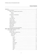
Page 2: ...2 Organization of Manual 12 Applicable Literature 12 Product Names 12 Agency Listings 13 Abbreviations 14 Constructions of Controller and Wall Module 14 Stryker CVAHU configuration by Zio wall module 15 Contractor Mode Introduction 15 Initial Power Up 16 Contractor Mode Configuration Steps 17 Set Home Screen 17 Set View More 18 Parameters 20 Sensors 21 Status 22 Temp Sp 25 Override 28 Alarms 28 Sn...

Page 3: ...STRYKER CVAHU ZIO CONFIGURATION GUIDE 3 AO2 44 AO3 45 Cnfg Out 46 Time 50 Set Time 51 Set Date 51 Schedule 53 Tenant Mode Introduction 54 Tenant Mode View Steps 54 Fan 55 Override 56 System View More 57 ...

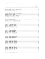
Page 4: ...rameter group Sensors 20 Figure 15 Parameters Sensors Zio Temp 20 Figure 16 Parameters Sensors Zio Temp 21 Figure 17 Parameter Status Htg Out 22 Figure 18 Parameter Status Clg Out 22 Figure 19 Parameter Status Damper 22 Figure 20 Parameter Status Dmd Limit 22 Figure 21 Parameter Status Trmnl Ld 23 Figure 22 Parameter Status Aux Econ 23 Figure 23 Parameter Status Free Mod 23 Figure 24 Parameter Sta...

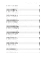
Page 5: ... Config Htgsp Lo 33 Figure 54 Parameter Wm Config Clgsp Hi 33 Figure 55 Parameter Wm Config Clgsp Lo 33 Figure 56 Parameter Wm Config Efhtg HI 34 Figure 57 Parameter Wm Config Efhtg Lo 34 Figure 58 Parameter Wm Config Efclg HI 34 Figure 59 Parameter Wm Config Efclg Lo 34 Figure 60 Parameter Cnfg Ctl Hp Type 35 Figure 61 Parameter Cnfg Ctl Clg Type 35 Figure 62 Parameter Cnfg Ctl Clg Tr 35 Figure 6...

Page 6: ... Parameter Time Time 50 Figure 92 Parameter Set Time Hours 51 Figure 93 Parameter Set Time Min 51 Figure 94 Parameter Set Date Year 51 Figure 95 Parameter Set Date Month 51 Figure 96 Parameter Set Date Day 52 Figure 97 Parameter Schedule 53 Figure 98 Parameter Schedule Monday 53 Figure 99 Parameter Schedule Monday Mon E1 53 Figure 100 Tenant mode home screen 54 Figure 101 Tenant mode Fan Auto 55 F...

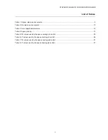
Page 7: ... documents 10 Table 3 List of applicable literature 12 Table 4 Agency listing 13 Table 5 TR values used by the space cooling pid control 35 Table 6 IT values used by the space cooling pid control 36 Table 7 TR values used by the space heating pid control 37 Table 8 IT values used by the space heating pid control 37 ...

Page 8: ...STRYKER CVAHU ZIO CONFIGURATION GUIDE 8 ...

Page 9: ...d a second microcontroller for LONWORKS network communications Each controller provides flexible universal inputs for external sensors digital inputs and a combination of analog outputs and digital outputs Features Uses the Echelon LONWORKS network protocol Free Topology Transceiver FTT high speed 78 kilobits communications network Capable of stand alone operation but may also use LONWORKS bus net...

Page 10: ...rameters in the controller Network bus jack Simple 2 wire terminal connection to the programmable controller includes power and an optional 2 wire terminal connection for the network All connections are polarity insensitive Permanent retention of user configuration including Setpoints after a power outage For more information refer below mentioned documents as shown in Table 2 Table 2 Zio referenc...

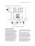
Page 11: ...cooling can be configured to one of the strategies based on the inputs When the economizer position is controlled from the Stryker CVAHU the minimum position setting for ventilation requirements is adjusted based on indoor air quality IAQ needs in the space IAQ monitoring is provided through either a CO2 sensor or a digital input from a space mounted IAQ limit switch For heat pump configurations u...

Page 12: ...iterature Form No Title 63 4529 03 Stryker Lon Configurable VAV CVAHU Controller Specification Data 62 2029 02 Stryker Lon Configurable VAV CVAHU Controller Installation Instructions 63 1322 02 Zio Zio Plus LCD Wall Modules Wall Module Specification Data 62 0271 07 Zio Zio Plus LCD Wall Modules Wall Module Installation Instructions 63 2719 LCD Wall Modules Wall operating guide 209541B LONWORKS Bus...

Page 13: ...UL Listed E87741 CSA LR95329 3 listed FCC Meets FCC Part 15 Subpart B Class B radiated emissions requirements Meets Canadian standard C108 8 radiated emissions CE Conforms to the following requirements per European Consortium standards EN 61000 6 1 2001 EU immunity EN 61000 6 3 2001 EU emissions Zio Zio Plus LCD wall modules TR70 TR71 TR75 with Sylk bus UL Not applicable cUL Not applicable CSA Not...

Page 14: ...ctuator open and another digital output to pulse it closed FTT Free Topology Transceiver IAQ Indoor Air Quality It refers to the quality of the air in the conditioned space as it relates to occupant health and comfort I O Input Output the physical sensors and actuators connected to a controller I R I times R or current times resistance refers to Ohm s Law V I x R K Degrees Kelvin NV Network Variab...

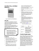
Page 15: ...re displayed You are then prompted to enter a password default 0000 Compatibility The TR70 Series LCD Wall Modules operate with the Sylk Enhanced Stryker controller The TR71 TR75 can replace a TR70 in an installation where an upgrade to WEBs AX or Stryker or reprogramming is not desired Features like scheduling additional memory etc are not available Likewise a TR71 is replaced by another TR71 or ...

Page 16: ...l number and Sylk bus address as shown in Figure 7 Figure 7 Model number and Sylk bus address On power up screen displays revision and Zio model number Controller features not supported by Zio configuration Network functionality Accessory loops Custom sensors Local sensor UI 1 4 calibration CVAHU controller default configuration Wall module Zio Center setpoint source Zio Center setpoint disabled c...

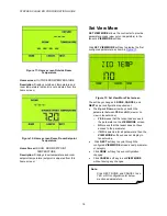
Page 17: ...Tenant view to show a subset or none of the configured parameters When the contractor clicks the SET HOME SCREEN soft key the display changes as shown in the Figure 9 to Figure 12 The soft keys change to DONE CANCEL and NEXT as per configuration requirement Click NEXT soft key to cycle through the configured home screens Click DONE soft key when the desired home screen to be set as default home sc...

Page 18: ...y the first configured parameter as shown in Figure 13 Figure 13 Set View More First screen The soft keys changes to DONE CANCEL and NEXT as per configuration requirement The Up and Down arrow keys switch the parameter between YES and NO view or no view in tenant mode o YES means that the tenant has access to the parameter on the VIEW MORE screen o NO means that the tenant does not have access to ...

Page 19: ...ST 36 IAQ ALM 37 INVLD SP 38 SPCTEMP 39 ZIO T OF 40 ZIO H OFF 41 UNITS 42 TYPE 43 CNTR SP 44 CNTSP HI 45 CNTSP LO 46 BYPS MIN 47 HTGSP HI 48 HTGSP LO 49 CLGSP HI 50 CLGSP LO 51 EFHTG HI 52 EFHTG LO 53 EFCLH HI 54 EFCLG LO 55 HP TYPE 56 CLG TYPE 57 CLG TR 58 CLG IT 59 HTG TYPE 60 HTG TR 61 HTG IT 62 FAN MODE 63 OC SNROP 64 UI1 65 UI2 66 UI3 67 UI4 68 UI5 69 UI6 70 DI1 71 DI2 72 DI3 73 DI4 74 SPC TE...

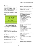
Page 20: ...example ZIO TEMP parameter in the SENSORS category as shown in Figure 15 Figure 15 Parameters Sensors Zio Temp If the parameter is configured as adjustable by the tenant the up and down arrow keys adjust the value of the parameter Click NEXT soft key to display the next parameter or category Click DONE soft key to save configuration changes Click CANCEL soft key to the exit PARAMETER group or PARA...

Page 21: ...d is an input to the Sbus wall module function block DISCHRG Displays discharge air temperature and is an input to the Sbus wall module function block OAT Displays outside air temperature and is an input to the Sbus wall module function block OAH Displays outside air humidity and is an input to the Sbus wall module function block OCC SNSR Displays occupancy sensor and is an input to the Sbus wall ...

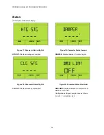
Page 22: ...ling output signal Figure 18 Parameter Status Clg Out CLG OUT Displays heating output signal Figure 19 Parameter Status Damper DAMPER Displays damper output signal Figure 20 Parameter Status Dmd Limit DMD LIMIT Displays demand limit setpoint shift status as ON or OFF Configuration settings in program are as follows 0 OFF 1 ON 255 OFF ...

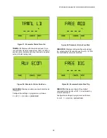
Page 23: ...isplays auxiliary economizer status as ON or OFF Configuration settings in program are as follows 0 OFF 1 ON 255 UNDEFINED Figure 23 Parameter Status Free Mod FREE MOD Displays configured free modulating1 output signal Its value ranges from 0 to 100 It is controlled by network command Figure 24 Parameter Status Free Dtg FREE DTG Displays configured free digital1 command status as ON or OFF It is c...

Page 24: ...STRYKER CVAHU ZIO CONFIGURATION GUIDE 24 Figure 25 Parameter Status Fan FAN Displays fan digital output status as ON or OFF Configuration settings in program are as follows 0 OFF 1 ON 255 UNDEFINED ...

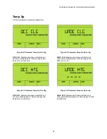
Page 25: ...igure 27 Parameter Temp Sp Occ Htg OCC HTG Displays and allows modification of occupied heating setpoint Its value ranges from EFHTG LO to EFHTG HI Figure 28 Parameter Temp Sp Unoc Clg UNOC CLG Displays and allows modification of unoccupied cooling setpoint Its value ranges from STBY CLG to 90 Figure 29 Parameter Temp Sp Unoc Htg UNOC HTG Displays and allows modification of unoccupied heating setp...

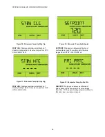
Page 26: ...ication of standby heating setpoint Its value ranges from OCC HTG to UNOC HTG Figure 32 Parameter Temp Sp Setpoint SETPOINT Displays and allows modification of centre setpoint read from wall module Its value ranges from CNTSP LO to CNTSP HI Figure 33 Parameter Temp Sp Frz Prtc FRG PRTC Displays and allows modification of Space freeze protection setpoint Its value ranges from 30 to 70 The space hea...

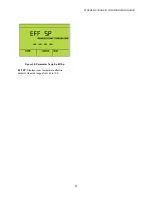
Page 27: ...STRYKER CVAHU ZIO CONFIGURATION GUIDE 27 Figure 34 Parameter Temp Sp Eff Sp EFF SP Displays room temperature effective setpoint Its value ranges from 40 to 100 ...

Page 28: ...ion settings in program are as follows 0 OFF 1 ON 255 UNDEFINED Alarms CVAHU parameter alarms Figure 36 Parameter Alarms Emrg Ovrd EMRG OVRD Displays smoke detector status as TRUE FALS or UNDEFINED Configuration settings in program are as follows 0 FALS 1 TRUE 255 UNDEFINED Figure 37 Parameter Alarms Clg Ovrd CLG OVRD Displays cooling override status as TRUE FALS or UNDEFINED Configuration setting...

Page 29: ... fan override status as TRUE FALS or UNDEFINED Configuration settings in program are as follows 0 FALS 1 TRUE 255 UNDEFINED Figure 40 Parameter Alarms Frost FROST Displays frost override status as TRUE FALS or UNDEFINED Configuration settings in program are as follows 0 FALS 1 TRUE 255 UNDEFINED Figure 41 Parameter Alarms Iaq Alm IAQ ALM Displays IAQ alarm override status as TRUE FALS or UNDEFINED...

Page 30: ...t override status as TRUE FALS or UNDEFINED Configuration settings in program are as follows 0 FALS 1 TRUE 255 UNDEFINED Figure 43 Parameter Alarms Spc Temp SPC TEMP Displays space temperature override status as TRUE FALS or UNDEFINED Configuration settings in program are as follows 0 FALS 1 TRUE 255 UNDEFINED ...

Page 31: ...le configuration Figure 46 Parameter Wm Config Units UNITS Displays and allows modification of units to be displayed for temperature parameters as C F UNDEFINED Default configuration UNDEFINED Configuration settings in program are as follows 0 F Deg F 1 C Deg C 255 UNDEFINED Figure 47 Parameter Wm Config Type TYPE Displays and allows modification of type for wall module to be used as NONE TR20 ZIO...

Page 32: ...re as follows 0 FALS 1 TRUE 255 UNDEFINED Figure 49 Parameter Wm Config Cntsp Hi CNTSP HI Displays and allows modification of centre setpoint high limit Its value ranges from CNTSP LO to 100 Figure 50 Parameter Wm Config Cntsp Lo CNTSP LO I Displays and allows modification of centre setpoint low limit Its value ranges from 10 to CNTSP HI Figure 51 Parameter Wm Config Byps Min BYPS MIN Displays and...

Page 33: ...nfig Htgsp Lo HTGSP LO Displays and allows modification of heating setpoint low limit Its value ranges from 0 to HTGSP HI Figure 54 Parameter Wm Config Clgsp Hi CLGSP HI Displays and allows modification of cooling setpoint high limit Its value ranges from CLGSP LO to 100 Figure 55 Parameter Wm Config Clgsp Lo CLGSP LO Displays and allows modification of cooling setpoint low limit Its value ranges ...

Page 34: ...s effective heating high setpoint Figure 57 Parameter Wm Config Efhtg Lo EFHTG LO Displays effective heating low setpoint Figure 58 Parameter Wm Config Efclg HI EFCLG HI Displays effective cooling high setpoint Figure 59 Parameter Wm Config Efclg Lo EFCLG LO Displays effective cooling low setpoint ...

Page 35: ...lt configuration 2STG Configuration settings in program are as follows 0 NONE 1 1STG 2 2STG 3 3STG 4 4STG 10 ANA Figure 62 Parameter Cnfg Ctl Clg Tr CLG TR Displays and allows modification of space cooling PID control throttling range Its value ranges from 0 to 30 F Throttling Range TR When TR is nonzero this value of TR is used by the space cooling PID control Auto Gain Selection When TR is 0 Tab...

Page 36: ... used by the space cooling pid control Type Without Economizer IT With Economizer IT 1stg 3333 2000 2stg 2000 1429 3stg 1429 1111 4stg 1111 909 Figure 64 Parameter Cnfg Ctl Htg Type HTG TYPE Displays and allows modification of heating output type for conventional or heat pump auxiliary heat as NONE 1STG 2STG 3STG 4STG ANA Default configuration 2STG Configuration settings in program are as follows ...

Page 37: ...e space heating PID control Table 7 TR values used by the space heating pid control Type TR 1stg 3 2stg 5 3stg 7 4stg 8 Figure 66 Parameter Cnfg Ctl Htg It HTG IT Displays and allows modification of heating PID control integral time Its value ranges from 0 to 5000 sec Integral Time IT When TR is nonzero this value of IT is used by the space heating PID control Auto Gain Selection When TR is 0 Tabl...

Page 38: ...P Displays and allows modification of occupancy sensor operation status This can be changed as CLN CONF TNNT and UNDEFINED Default configuration UNDEFINED Configuration settings in program are as follows 1 CLN Unoccupied Cleaning Crew when scheduled to be unoccupied and the occupancy sensor is active switch to standby for the comfort of the cleaning crew 2 CONF Conference Room when scheduled to be...

Page 39: ...T the following parameters are available with configuration settings similar to UI1 UI2 Universal Input2 UI3 Universal Input3 UI4 Universal Input4 UI5 Universal Input5 UI6 Universal Input6 Cnfg Di Configuration of CVAHU digital inputs Figure 70 Parameter Cnfg Di Di 1 DI 1 Displays and allows modification of input type for digital input 1 This can be changed as DGNO DGNC and UNDEFINED Default confi...

Page 40: ... Parameter setting UNDEFINED Configuration settings in program are as follows 0 UI 1 1 UI 2 2 UI 3 3 UI 4 4 UI 5 5 UI 6 7 ZIO 255 UNDEFINED Figure 72 Parameter Cnfg In Spe Rh SPC RH Displays and allows modification of logical input configuration terminal assignment for space relative humidity This can be changed as UI 1 UI 2 UI 3 UI 4 UI 5 UI 6 ZIO and UNDEFINED Default Parameter setting UNDEFINED...

Page 41: ...ment for discharge air temperature This can be changed as UI 1 UI 2 UI 3 UI 4 UI 5 UI 6 SB8 SB9 SB10 SB11 SB12 and UNDEFINED Default Parameter setting UNDEFINED Configuration settings in program are as follows 0 UI 1 1 UI 2 2 UI 3 3 UI 4 4 UI 5 5 UI 6 21 SB8 C7400s temperature bus Address 8 22 SB9 C7400s temperature bus Address 9 23 SB10 C7400s temperature bus Address 10 24 SB11 C7400s temperature...

Page 42: ...perature bus Address 10 24 SB11 C7400s temperature bus Address 11 25 SB12 C7400s temperature bus Address 12 255 UNDEFINED Figure 76 Parameter Cnfg In Od Temp OD TEMP Displays and allows modification of logical input configuration terminal assignment for outside air temperature This can be changed as UI 1 UI 2 UI 3 UI 4 UI 5 UI 6 SB8 SB9 SB10 SB11 SB12 and UNDEFINED Default Parameter setting UNDEFI...

Page 43: ... settings in program are as follows 0 UI 1 1 UI 2 2 UI 3 3 UI 4 4 UI 5 5 UI 6 47 DI 1 48 DI 2 49 DI 3 50 DI 4 255 UNDEFINED Figure 78 Parameter Cnfg In Window WINDOW Displays and allows modification of logical input configuration terminal assignment for window contacts This can be changed as UI 1 UI 2 UI 3 UI 4 UI 5 UI 6 DI 1 DI 2 DI 3 DI 4 and UNDEFINED Default Parameter setting UNDEFINED Configu...

Page 44: ...ent 4 to 20 mA direct output 9 20A4 Analog current 4 to 20 mA reverse output 10 DIG Analog as binary output 255 UNDEFINED AO2 Analog output2 range configuration Figure 80 Parameter AO2 Range RANGE Displays and allows modification of analog output2 range This can be changed as 0D10 10D0 2D10 10D2 0A20 20A0 0A22 22A0 4A20 20A4 DIG and UNDEFINED Default Parameter setting UNDEFINED Configuration setti...

Page 45: ... are as follows 0 0D10 Analog voltage 0 to 10VDC direct output 1 10D0 Analog voltage 0 to 10VDC reverse output 2 2D10 Analog voltage 2 to 10VDC direct output 3 10D2 Analog voltage 2 to 10VDC reverse output 4 0A20 Analog current 0 to 20 mA direct output 5 20A0 Analog current 0 to 20 mA reverse output 6 0A22 Analog current 0 to 22 mA direct output 7 22A0 Analog current 0 to 22 mA reverse output 8 4A...

Page 46: ... in program are as follows 0 AO 1 1 AO 2 2 DOC1 DO1 3 DOA1 DO2 4 DOA2 DO3 5 DOA3 DO4 6 DOB1 DO5 7 DOB2 DO6 8 DOB3 DO7 9 DOB4 DO8 10 AO 3 255 UNDEFINED Figure 83 Parameter Cnfg Out Clg Stg2 CLG STG2 Displays and allows modification of logical output configuration terminal assignment for Cooling or Heat Pump stage 2 Command This can be changed as AO 1 AO 2 DOC1 DOA1 DOA2 DOA3 DOB1 DOB2 DOB3 DOB4 AO ...

Page 47: ...0 AO 1 1 AO 2 2 DOC1 DO1 3 DOA1 DO2 4 DOA2 DO3 5 DOA3 DO4 6 DOB1 DO5 7 DOB2 DO6 8 DOB3 DO7 9 DOB4 DO8 10 AO 3 255 UNDEFINED Figure 85 Parameter Cnfg Out Hp Chang HP CHANG Displays and allows modification of logical output configuration terminal assignment Heat Pump change over relay command This can be changed as AO 1 AO 2 DOC1 DOA1 DOA2 DOA3 DOB1 DOB2 DOB3 DOB4 AO 3 and UNDEFINED Default Paramete...

Page 48: ...AO 1 1 AO 2 2 DOC1 DO1 3 DOA1 DO2 4 DOA2 DO3 5 DOA3 DO4 6 DOB1 DO5 7 DOB2 DO6 8 DOB3 DO7 9 DOB4 DO8 10 AO 3 255 UNDEFINED Figure 87 Parameter Cnfg Out Htg Stg2 HTG STG2 Displays and allows modification of logical output configuration terminal assignment for Heating stage 2 Command This can be changed as AO 1 AO 2 DOC1 DOA1 DOA2 DOA3 DOB1 DOB2 DOB3 DOB4 AO 3 and UNDEFINED Default Parameter setting ...

Page 49: ... AO 1 1 AO 2 2 DOC1 DO1 3 DOA1 DO2 4 DOA2 DO3 5 DOA3 DO4 6 DOB1 DO5 7 DOB2 DO6 8 DOB3 DO7 9 DOB4 DO8 10 AO 3 255 UNDEFINED Figure 89 Parameter Cnfg Out Fan Out FAN OUT Displays and allows modification of logical output configuration terminal assignment for Fan Start Stop Command This can be changed as AO 1 AO 2 DOC1 DOA1 DOA2 DOA3 DOB1 DOB2 DOB3 DOB4 AO 3 and UNDEFINED Default Parameter setting UN...

Page 50: ...nfiguration terminal assignment for Damper control signal This can be changed as AO 1 AO 2 AO 3 and UNDEFINED Default Parameter setting UNDEFINED Configuration settings in program are as follows 0 AO 1 1 AO 2 10 AO 3 255 UNDEFINED Time CVAHU controller time display Figure 91 Parameter Time Time TIME Displays current time in HH MM format ...

Page 51: ...Figure 93 Parameter Set Time Min MIN Displays and allows modification of time in minutes Its value ranges from 0 to 59 Set Date CVAHU controller date configuration settings Figure 94 Parameter Set Date Year YEAR Displays and allows modification of date in years Its value ranges from 2008 to 2099 Figure 95 Parameter Set Date Month MONTH Displays and allows modification of date in months Its value r...

Page 52: ...STRYKER CVAHU ZIO CONFIGURATION GUIDE 52 Figure 96 Parameter Set Date Day DAY Displays and allows modification of date in days Its value ranges from 0 to 31 ...

Page 53: ... key to toggle between editing the time and changing the occupancy state i e OCC UNOCC STANDBY 3 Use the up down arrows to change occupancy state 4 Click DONE soft key to apply changed time and occupancy state settings 5 Click CANCEL soft key to exit the MON E1 screen display without saving any changes 6 Click NEXT and follow above mentioned steps 1 to step 6 to view or edit next three events i e ...

Page 54: ...referring to Figure 100 Tenant mode home screen has the following three soft keys They provide the following options which are explained below in detail 1 Fan 2 Override 3 System and view mode Note Tenant mode default home screen may be in any one of out of above mentioned four home screen set by the contractor Refer Set Home Screen Note 1 The fan and override settings are optional for home screen...

Page 55: ...n AUTO Operates in Auto mode Refer Figure 101 ON Operates in manual ON mode Refer Figure 102 OFF Operates in manual OFF mode Refer Figure 103 2 ON Figure 102 Tenant mode Fan On 3 OFF Figure 103 Tenant mode Fan Off Click the FAN softkey to toggle the fan icon between ON and AUTO If the fan is at 2 positions then each click on the FAN soft key changes the fan icon display between ON and AUTO At posi...

Page 56: ...rride For example if occupied duration is 9 00 AM to 6 00 PM and override operation is configured for one hour and if override is applied at 6 PM then override remaining will be 25 minutes at 6 35 PM Depending on the occupancy override configuration click the OVERRIDE soft key The occupancy icon changes to one of the following three modes o Standby o Occupied o Unoccupied If an override is set by ...

Page 57: ...nfiguration changes Click the CANCEL soft key to exit the display without saving any changes Click VIEW MORE soft key to display each viewable parameter For example Figure 106 Tenant mode Room Temp ROOM TEMP Displays room temperature and is an input to the Sbus wall model function block Use the UP DOWN arrow keys on Zio module to increase or decrease the value or state for tenant adjustable parame...

Page 58: ...ock Figure 109 Tenant mode Eff Sp EFF SP Displays effective setpoint and is an input to the Sbus wall model function block Figure 110 Tenant mode Cntr Sp CNTR SP Displays and allows modification of centre setpoint It is both an input and output to the Sbus wall model function block Figure 111 Tenant mode Time TIME Displays controller time in HH MM format ...

Page 59: ...s modification of time in minutes Its value ranges from 0 to 59 Figure 113 Tenant Mode Min HOURS Displays and allows modification of time in hours Its value ranges from 0 to 11 Figure 114 Tenant Mode Year YEAR Displays and allows modification of date in years Its value ranges from 2008 to 2099 ...

Page 60: ...ers Neuron LONWORKS LONMARK are registered trademarks of Echelon Corporation Automation and Control Solutions Honeywell International Inc 1985 Douglas Drive North Golden Valley MN 55422 http www customer honeywell com U S Registered Trademark 2013 Honeywell International Inc C G 11 2013 31 00023 01 Printed in United States ...

Reviews: