


WEB-300E, WEB-600E/U, CP-300E, CP-600E/U SERIES CONTROLLERS
31-00010—01
2
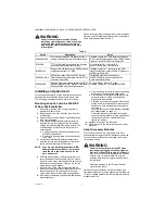
Table 1.
PREPARATION
Unpack the controller and inspect the package contents
for damaged or missing components. If damaged, notify
the appropriate carrier at once and return any damaged
components for immediate repair or replacement. See
“Returning a Defective Unit” on page 17.
Included in this Package
Included in this package you should find the following items:
• A WEB-300E, WEB-300E-O, CP-300E, WEB-600E/U,
WEB-600E-O/U, or a CP-600E/U controller.
• WEB-300E, WEB-600E/U, CP-300E, CP-600E/U
Series Controllers Installation Instructions (31-00010).
• a hardware bag containing the following items:
—
One (1) grounding wire, with quick-disconnect
0.187" female connector.
Material and Tools Required
The following supplies and tools are typically required for
installation:
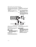
• A suitable power module, as one of the following types:
— NPB-PWR
-H/U
: 24Vac or 24Vdc, in-line, DIN
mount capable, with grounding wire.
— NPB-PWR-UN
-H/U
: 120–240Vac, in-line, DIN
mount capable, with grounding wire.
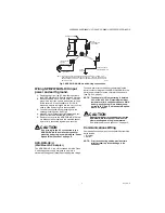
— NPB-WPM-US/U: External wall-mount power
adapter.
NOTE: Using an NPB-PWR-H/U power module pro-
vides the widest operating temperature
range. See “Environmental Requirements”
• If using a NPB-PWR-H/U (24V) power module, either
one of the following:
— UL listed, Class 2, 24Vac transformer, rated at min-
imum of 7.5VA to 20VA (approximate range of con-
troller alone, to fully-expanded unit with four
additional IO-16-H/U modules and other option
boards). Note that a dedicated transformer is
required (cannot also power additional equipment).
— 24Vdc power supply, capable of supplying at
least 1A (24W).
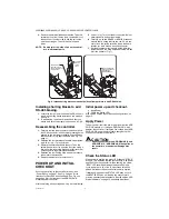
• DIN rail, type NS35/7.5 (35mm x 7.5mm) and DIN rail
end-clips (stop clips), recommended for any
installation that includes NPB-PWR-H/U or
NPB-PWR-UN-H/U power module and/or
optional I/O modules.
• Suitable tools and fasteners for mounting unit and
accessories.
• #2 phillips screwdriver: used to install and remove any
option card.
• Small flat-blade screwdriver: used for making wiring
connections to removable screw terminal plugs, also
for mounting and removing modules from DIN rail.
Model
Description
WEB-300E
WEB-300E, includes two Ethernet ports, one RS-232 port, and one RS-485 port. Web User
Interface and Niagara Connectivity included. oBIX Client/Server driver included.
WEB-300E-O
WEB-300E with Open License, includes two Ethernet ports, one RS-232 port, and one RS-485
port. Web User Interface and Niagara Connectivity included. oBIX Client/Server driver included.
CP-300E
Comfort Point 300E, includes two Ethernet ports, one RS-232 port, and one RS-485 port. Web
User Interface and Niagara Connectivity included. oBIX Client/Server driver included.
WEB-600E/U
The WEB-600E/U is designed for Battery less operation and DIN rail mounting. Standard features
include WEBs-AX station and Web User Interface. Standard drivers include oBIX Client / Server
and Niagara Network (Fox) Client / Server.
WEB-600E-O/U
The WEB-600E-O/U with Open License is designed for Battery less operation and DIN rail
mounting. Standard features include WEBs-AX station and Web User Interface. Standard drivers
include oBIX Client / Server and Niagara Network (Fox) Client / Server.
WEB-600E-US/U
The WEB-600E-US/U is designed for Battery less operation and DIN rail mounting. Standard
features include WEBs-AX station and Web User Interface. Standard drivers include oBIX Client /
Server and Niagara Network (Fox) Client / Server. Made in USA controller.
WEB-600E-US-O/U
The WEB-600E-US-O/U with Open License is designed for Battery less operation and DIN rail
mounting. Standard features include WEBs-AX station and Web User Interface. Standard drivers
include oBIX Client / Server and Niagara Network (Fox) Client / Server. Made in USA controller.
CP-600E/U
The CP-600E/U is designed for Battery less operation and DIN rail mounting. Standard features
include CP-AX station and Web User Interface. Standard drivers include oBIX Client / Server and
Niagara Network (Fox) Client / Server.
WEB-300E-AX-DEMO
Base Unit including two Ethernet ports, one RS-232 port, and one RS-485 port. Web User
Interface and Niagara Connectivity included. oBIX Client/Server driver included. Includes NPB-
WPM-US/U, NPB-LON/U, NPB-2X-RS485/U, IO-16-REM-H/U, NPB-BATTERY/U, NPB-RS232/U.
Requires AX release 3.7.106 or higher.
CP-300E-DEMO
Base Unit including two Ethernet ports, one RS-232 port, and one RS-485 port. Web User
Interface and Niagara Connectivity included. oBIX Client/Server driver included. Includes NPB-
WPM-US/U, NPB-LON/U, NPB-2X-RS485/U, IO-16-REM-H/U, NPB-BATTERY/U, NPB-RS232/U.
Requires AX release 3.7.106 or higher.
W-600E-AX-DEMO/U
Office Demo WEB 600E Controller
CP-600E-AX-DEMO/U
Comfort Point 600E Demo Controller
NPB-PWR-H/U
24Vac/dc input/15Vdc output power supply module, DIN mountable.
NPB-PWR-UN-H/U
120–240Vac universal input/15Vdc output power supply module, DIN mountable.
NPB-WPM-US/U
Wall Adaptor (US)