


WEB-300E, WEB-600E/U, CP-300E, CP-600E/U SERIES CONTROLLERS
31-00010—01
10
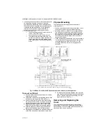
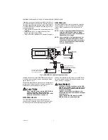
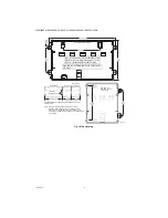
Fig. 6. WEB/CP 300E or WEB/CP 600E/U controller bottom side (cover removed).
Ethernet
Two, female 10/100-Mbit Ethernet connections are provided
on the controller. These RJ-45 connectors are labeled
LAN1 (PRI) and LAN2 (SEC). Use a standard Ethernet
patch cable for connecting to a hub or Ethernet switch.
The factory-default IP address for LAN1 is
192.168.1.12
n
, where the last numeral
n
in the
address matches the last digit in the controller’s serial
number, and the subnet mask is
255.255.255.0
. By
default, LAN2 is disabled.
NOTE: Typically, you
only use LAN1
(primary port),
unless you have a specific application for the
other LAN2 port. For example, isolating a driver’s
network traffic, using LAN2. Do
not
use LAN2 as
the primary port.
If enabling LAN2, note that LAN1 and LAN2 must
be connected to
different subnets
. Further, a
controller
does not provide IP routing or bridg-
ing operation
between the two LAN ports.
Refer to the
JACE WEBs-AX Install and Startup Guide
for
details on changing IP address using the platform
Commissioning Wizard (TCP/IP configuration step).
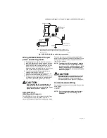
Serial
There are two “RS” serial ports on the controller’s base
board. Each has a UART capable of operation up to
115,200 baud. At the bottom of the board (see Fig. 6) is
an RS-232 port using an DB-9 plug (male) connector. To
the right of this is a two-wire plus shield RS-485 port,
using a 3-position screw-terminal connector plug.
NOTE: A green “receive” LED and yellow “transmit”
LED are provided for both serial ports. These
LEDs are on the controller’s bottom board,
on the side opposite to the serial connectors
(see Fig. 3 on page 5). These LEDs are
labeled on the board (COM1, COM2) and are
not visible with the cover on.
RS-232
An RS-232 serial port using a male DB-9 connector
always operates as COM1. You can use standard DB-9
serial cables with this port.
The controller is a serial DTE device, such that another
DTE device (PC, for example) requires a “null modem”
cable. If connecting to a DCE device such as a modem,
use a straight-through cable. Table 4 provides standard
serial DB-9 pinouts.
NOTE: If rebooted with the mode jumper in the
“Serial Shell” position (see Fig. 3 on page 5),
the RS-232 port provides “system shell”
access. See the JACE WEBs-AX Install and
Startup Guide for related details.
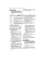
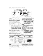
Table 4. Base serial port (RS-232 and RS-485) pinouts.
RS-485
An RS-485 port uses a 3-position, screw terminal
connector, and always operates as COM2. As shown in
the Table 4 pinouts, from left-to-right the screw terminals
are shield (S), plus (+), and minus (–). Wire in a
continuous multidrop fashion to other RS-485 devices,
meaning “minus to minus”, “plus to plus,” and “shield to
shield.” Connect the shield to earth ground at one end
only, such as at the controller.
EARTH GROUND
SPADE LUG
PRIMARY ETHERNET (RJ-45)
LAN 1
SECONDARY ETHERNET (RJ-45)
LAN 2
OPTIONAL NIMH BATTERY
AND BRACKET ASSEMBLY, IF
INSTALLED, MOUNTS ON TOP
OF THE OPTION SLOT AREA.
RS-485
(3-POS.)
COM2
RS-232
(DB-9)
COM1
BARREL POWER
CONNECTOR FOR
WPM-XXX (WALL
MOUNT AC ADAPTER)
20-PIN
CONNECTOR
(I/O AND
POWER MODULES)
OPTION
SLOT AREA
(SLOT #1
THIS SIDE)
M34993
Base RS-232 DB-9 Port (COM1)
RS-485 Port (COM2)
Pinout Reference
Signal
DB-9
Pinouts
DB-9 Plug (male)
DCD
Data carrier detect
1
3-Position connector (male)
S + –
RXD
Receive data
2
TXD
Transmit data
3
DTR
Data terminal ready
4
GND
Ground
5
DSR
Data set ready
6
RTS
Request to send
7
CTS
Clear to send
8
not used on the controller
9