Honeywell CP-300E Series Installation Instructions Manual Download Page 17

WEB-300E, WEB-600E/U, CP-300E, CP-600E/U SERIES CONTROLLERS

17

31-00010—01

8.

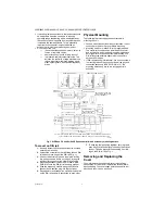
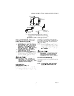
Check the RS-485 biasing jumpers on the existing 

unit, and duplicate on the replacement unit (See 

“Disassembling the controller.” on page 11.)

9.

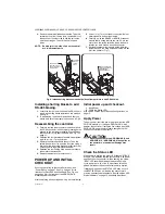
Mount the replacement controller as it was previ-

ously, using the same DIN rail location and/or 

screws.

10.

Reconnect/remount any removed accessory mod-

ules, being careful to replace in the same order, 

using the same DIN rail location and/or screws. 

Secure all modules as done previously.

11.

Reconnect the earth ground wire to the controller’s 

grounding lug and any installed accessory modules.

12.

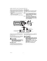
Reconnect any Ethernet, serial, modem, and I/O 

connectors.

13.

If using IO modules, and any of your I/O points have 

voltage, turn the devices back on, or reconnect 

power to them.

14.

Replace the cover. See “Removing and Replacing 

the Cover” on page 4.

15.

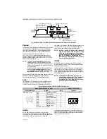
Restore power to the unit. It should boot up as a 

new unit (See “Check the Status LED” on page 12.).

16.

Using the WEBs-AX platform tools, re-commission 

the controller, and install the saved station data-

base. For more details, see the

 JACE WEBs-AX 

Install and Startup Guide.

Returning a Defective Unit

For proper credit on an in-warranty unit, ship the defective 

unit per the vendor’s return material procedures.

NOTE: If the defective unit is under warranty, please 

follow return instructions provided in this 

section.

If the unit is out of warranty, please discard 

any replaced part. Do not return an out-of-

warranty  controller.

Prior to returning the unit, contact your vendor to obtain a 

return materials authorization (RMA) number and other 

instructions.

Please provide:
• Product model

• Serial number

• Nature of the defect

• PO number to secure the RMA

CERTIFICATIONS

The WEB/CP-300E and WEB/CP-600E/U controller each 

has the following agency listings, compliances, and 

certifications:

• UL 916 - Underwriters Laboratories, Energy 

Management Device, CAN/CSA C22.2 Canadian 

Safety Standards

• FCC Part 15, Class B - Federal Communications 

Commission

• ICES-003, Class B - Industry Canada Interference-

Causing Equipment Standard

• EU 202/95/EC RoHS (Restriction of Hazardous 

Substances)

• CE Declaration of Conformity (Council Directive 004-

108-EC)

For complete details on listings and compliances for these 

controllers, refer to the document 

Agency Listings and 

Approvals for Tridium Hardware Products

.

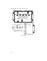
TAB MOUNTING DIMENSIONS

Measurements are in inches and (mm). Note that DIN 

mounting is recommended over tab mounting. See Fig. 1 

on page 4.

Summary of Contents for CP-300E Series

Page 1: ... system installation Instructions in this document apply to the products listed in Table 1 Not covered in this document is the WEBs AX software installation and configuration required for a fully functioning unit In addition the mounting and wiring of JACE expansion options are covered in separate documents See Related Documentation on this page and Expansion Options on page 5 Related Documentatio...

Page 2: ...des two Ethernet ports one RS 232 port and one RS 485 port Web User Interface and Niagara Connectivity included oBIX Client Server driver included CP 300E Comfort Point 300E includes two Ethernet ports one RS 232 port and one RS 485 port Web User Interface and Niagara Connectivity included oBIX Client Server driver included WEB 600E U The WEB 600E U is designed for Battery less operation and DIN r...

Page 3: ...any static electricity you may have accumulated Discharge static electricity by touching a known securely grounded object Do not handle printed circuit boards PCBs without proper protection against static discharge Use a wrist strap when handling PCBs The wrist strap clamp must be secured to earth ground Battery Precautions CAUTION The optional NiMH battery used in this device may present a risk o...

Page 4: ...er and accessory mounting details To mount on DIN rail 1 Securely install the DIN rail with at least two screws near the two rail ends 2 Position the controller on the rail tilting to hook DIN rail tabs over one edge of the DIN rail Fig 1 3 Use a screwdriver to pry down the plastic locking clip and push down and in on the unit forcing the locking clip to snap over the other DIN rail edge 4 Mount a...

Page 5: ...PTIONS The controller provides for field installable expansion using these types of options Option cards Install on connectors on the controller s base board See About Option Cards on page 5 Accessory modules To chain on the controller s 20 pin connector See About Accessory Modules on page 6 About Option Cards The controller has two 2 available option slots for option cards designed for use with c...

Page 6: ... aligned with the standoffs c Place the four screws through the bracket end plates and into the standoffs on the controller base board With a screwdriver hand tighten the screws For more details see NiMH Battery Installation and Maintenance on page 14 Otherwise place the two screws through the option card end plate and into the standoffs on the base board With a screwdriver hand tighten the screws...

Page 7: ...ller power NOTE See Environmental Requirements on page 3 for mains supply requirements The controller does not include an on off switch To apply power you either if NPB PWR H U plug in its 2 position power connector if NPB PWR UN H U energize the AC circuit 120 240 Vac wired to that module if NPB WPM US U plug in the power connector to the controller CAUTION Do not connect both the NPB WPM US U an...

Page 8: ...module is a 2 position power connector and an earth ground spade lug as shown in Fig 4 Connect the supplied earth ground wire to a nearby earth ground point Unplug the power connector plug from the module and make connections to it as shown CAUTION Do not plug 24V power into the NPB PWR H U reinsert connector plug until all other mounting and wiring is completed See Initial power up and checkout o...

Page 9: ... isolated Class 2 switching power supply designed to plug into a standard building power receptacle of appropriate voltage To supply power to the controller you simply plug the barrel connector plug from the NPB WPM US U into the barrel power connector on the controller s base board see Fig 3 on page 5 NOTE The adapter s 15W output rating is derated 50 at the 60 C 140 F maximum ambient temperature...

Page 10: ...he serial connectors see Fig 3 on page 5 These LEDs are labeled on the board COM1 COM2 and are not visible with the cover on RS 232 An RS 232 serial port using a male DB 9 connector always operates as COM1 You can use standard DB 9 serial cables with this port The controller is a serial DTE device such that another DTE device PC for example requires a null modem cable If connecting to a DCE device...

Page 11: ...ross the and terminals Termi nation resistors are typically 100 or 120 ohm value resistors Whenever termination resistors are used RS 485 biasing is typically required Adding RS 485 Bias To add biasing you must power off the controller and remove a few assemblies such as metal shield and NPM3E or NPM6E processor module to access the base board jumper pins located behind the RS 485 port Then you mu...

Page 12: ...own over the other side Make sure that its corner holes align with the metal standoffs below 4 Refasten the four Phillips head screws that secure the shield to the standoffs 5 Replace the plastic cover onto the unit POWER UP AND INITIAL CHECKOUT Ensure power wiring to the controller is ready see Power Wiring on page 7 See Fig 3 page 4 for the location of status LEDs and connectors See Fig 4 on pag...

Page 13: ...atform service An example is a station with many rapidly changing values all captured as histories on COV In this case you may wish to disable SRAM support and install and use only the optional NiMH battery pack For an overview see About Backup Configurations on page 13 Complete WEBs AX details on the operation of the controller s integral SRAM are in the JACE Data Recovery Service SRAM support En...

Page 14: ...s for the two serial ports are located on the controller s bottom board on the opposite side of the RS 232 and RS 485 ports Labels COM1 and COM2 correspond to the software configuration of the COM ports LEDs show the transmit and receive activity for the serial ports and optional modem NOTE You must remove the cover to see these LEDs See Removing and Replacing the Cover on page 4 The yellow transm...

Page 15: ...hand tighten these screws 10 Replace the cover 11 Restore power to the controller and verify normal operation Battery maintenance Battery life expectancy is a function of its discharge cycles the number of discharges and their depth and the ambient temperature of the battery during normal operation In most applications the NiMH battery should see relatively few discharges Therefore ambient tempera...

Page 16: ... section on page 6 To replace a controller with a new replacement unit proceed as follows REPLACING A WEB CP 300E OR WEB CP 600E U CONTROLLER 1 If possible use the appropriate WEBs AX software tool to back up the controller s configuration to your PC 2 Remove power to the controller The unit should power down automatically Wait for all LEDs to remain off NOTE If IO accessory modules are installed ...

Page 17: ...ning a Defective Unit For proper credit on an in warranty unit ship the defective unit per the vendor s return material procedures NOTE If the defective unit is under warranty please follow return instructions provided in this section If the unit is out of warranty please discard any replaced part Do not return an out of warranty controller Prior to returning the unit contact your vendor to obtain...

Page 18: ...MENDED OVER TAB MOUNTING SEE FIGURE 1 WEB 300E OR WEB 600E U NPB PWR H U NPB PWR UN H U OR IO 16 H U DISTANCE BETWEEN CENTER OF TABS FROM ONE UNIT TO ANOTHER UNIT NOTE IF MOUNTING ACCESSORY MODULES FUTURE REMOVAL REPLACEMENT OF THE CONTROLLER IS SIMPLIFIED IF YOU DO NOT INSTALL SCREWS IN THE ACCESSORY MODULE SIDE TABS OF THE CONTROLLER SEE ABOVE ACCESSORY MODULE SIDE TABS M35000 6 23 32 171 2 1 2 ...

Page 19: ...WEB 300E WEB 600E U CP 300E CP 600E U SERIES CONTROLLERS 19 31 00010 01 ...

Page 20: ...national Inc 31 00010 01 M S 09 13 Printed in United States By using this Honeywell literature you agree that Honeywell will have no liability for any damages arising out of your use or modification to the literature You will defend and indemnify Honeywell its affiliates and subsidiaries from and against any liability cost or damages including attorneys fees arising out of or resulting from any mo...

Reviews: