background image

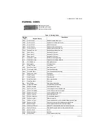
HONEYWELL CORE DRIVE

17

62-0410—04

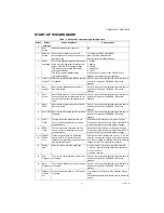
START-UP WIZARD GUIDE

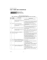
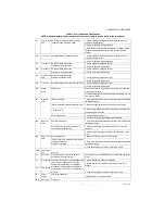
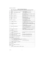
Table 11. Honeywell Commissioning Start-Up Wizard

Screen 

#

Screen 

Verbiage

Screen Description

Screen options

1

Boot 
Screen

Honeywell displayed for 3 seconds

N/A

2

Selection 
Screen

Choose how to interact with the VFD: 
Recommendation: Press function key F4 to 
start the wizard

F4: Initials the START UP WIZARD
Menu: redirects to MAIN MENU
ESC: redirects to MONITOR Screen

3

Select 
Language

Choose the keypad programming language
Use UP and DOWN arrows to change from 
default. Press ENTER to accept change.
F1 BACK up one menu (SAME function 
throughout WIZARD)
F4 Next Parameter (SAME function 
throughout WIZARD)

1. English
2. Spanish
3. Chinese
4. Portuguese
5. French
Use arrow keys to adjust. Press ENTER to save 
changes, F4 to advance without changes.

4

Clock Time 
and DATE

Select the time (Military) HH:MM:SS and date 
YY/MM/DD

Press F4 to accept factory defaults. Use arrow keys to 
adjust ONLY if needed. PRESS ENTER to save 
changes.

5

Motor 
Voltage

Motor's rated voltage based upon Motor 
Name Plate data

Press F4 to accept factory defaults. Use arrow keys to 
adjust ONLY if needed. PRESS ENTER to save 
changes.

6

Motor 
Current

Motor's rated current in FLA, Full Load AMPs 
based upon Motor Name Plate data. Do not 
use motor service factor amperage for this 
value.

Press F4 to accept factory defaults. Use arrow keys to 
adjust ONLY if needed. PRESS ENTER to save 
changes.

7

Motor 
FREQ

Motor's rated frequency based upon Motor 
Name Plate data

Press F4 to accept factory defaults. Use arrow keys to 
adjust ONLY if needed. PRESS ENTER to save 
changes.

8

Motor RPM Motor's rated RPM based upon Motor Name 

Plate data

Press F4 to accept factory defaults. Use arrow keys to 
adjust ONLY if needed. PRESS ENTER to save 
changes.

9

ACCEL 
TIME

The time required to accelerate from the 
motor’s current speed reference to a new 
speed reference

Acceleration time is factory set for typical Fan and 
Pump needs. Use arrow keys to adjust. Press ENTER 
to save changes, F4 to advance without changes.

10

DECEL 
TIME

The time required to decelerate from the 
motor’s current speed reference to a new 
speed reference

Decceleration time is factory set for typical Fan and 
Pump needs. Use arrow keys to adjust. Press ENTER 
to save changes, F4 to advance without changes.

11, 12, 

13

PRESET 
SPEED 
1,2,3

Present Speed options. On digital input 
closure the VFD will ignore the speed 
reference from the analog input and will run at 
the programmed speed.

With the use of MFI (Multifunction inputs) 1, 2, or 3 the 
drive can be sent to the programmed speed on digital 
input closure (Usage not required in the field). Adjust as 
needed or press F4 to accept factory defaults.

14

Analog 
Input

Select the speed reference signal type. 

0. 0-10V - Use AVI (Analog Voltage Input terminal)
1. 4-20mA - Use ACI (Analog current input terminals)
2. 2-10V - Use AVI
3. 0-20mA - Use ACI

15

MIN 
Frequency

The minimum frequency at which the motor 
will operate

Press F4 to accept factory defaults. Use arrow keys to 
adjust ONLY if needed. PRESS ENTER to save 
changes.

16

MAX 
Frequency

The maximum frequency at which the motor 
will operate

Press F4 to accept factory defaults. Use arrow keys to 
adjust ONLY if needed. PRESS ENTER to save 
changes.

17

PRESS F4 
to SAVE 
ALL

Saves all parameter updates - VFD is ready 
to operate

F1 will escape the user back to the Selection Screen 
again
F4 will save parameters and take the user to the display 
screen

Summary of Contents for CORE Drive

Page 1: ...on Storage and Transportation 3 Specification Tables 4 Minimum Mounting Clearances 7 Specifications for Wiring Terminals 9 Frame A 11 Frame B 12 Frame C 12 Frame D 13 Frame E 14 KeypadBasics 15 Start up Wizard Guide 17 Menu Structure 18 Warning Codes and Descriptions 19 Fault Codes and Descriptions 20 Wiring Diagrams 23 H W Q 0 5012613200 2011 11 ...

Page 2: ...ge level is reached DO NOT install the VFD in a place subjected to high temperature direct sunlight and inflammable materials See specification data in this manual for details WARNING Never apply power to the output terminals U T1 V T2 W T3 of the VFD Please stop operation immediately when a fault occurs during operation of the VFD and motor and refer to fault code information to reset the drive D...

Page 3: ...is installed at altitude 0 1000m follow normal operation restriction If it is installed at altitude 1000 3000m decrease 2 of rated current or lower 0 5o C of temperature for every 100m increase in altitude Maximum altitude for Corner Grounded is 2000m Package Drop Storage ISTA procedure 1A according to weight IEC60068 2 31 Transportation Vibration 1 0mm peak to peak value range from 2Hz to 13 2 Hz...

Page 4: ...itch S curve accel deccel 3 wire sequence Auto Tuning rotational stationary Frequency upper lower limit settings Cooling fan on off switch Slip compensation Torque compensation JOG frequency MODBus communication RS 485 RJ45 max 115 2 kbps DC injection braking at start stop Smart Stall PID control with sleep function Energy saving control Fan Control 230V series Model HCRDA0200B1000T 20HP and above...

Page 5: ... 4 6 8 10 13 20 26 30 36 48 58 72 86 102 Rated Output Current A 4 6 5 8 11 17 25 33 49 65 75 90 120 146 180 215 255 Applicable Motor Output kW 0 4 0 75 1 5 2 2 3 7 5 5 7 5 11 15 18 5 22 30 37 45 55 75 Applicable Motor Output HP 0 5 1 2 3 5 7 5 10 15 20 25 30 40 50 60 75 100 Overload tolerance 120 of rated current for 1 minute 160 of rated current for 3 seconds Max output frequency Hz 600 00Hz 55KW...

Page 6: ...8 58 73 88 120 Rated Output Current A 2 8 3 4 6 10 5 12 18 24 32 38 45 60 73 91 110 150 Applicable Motor Output kW 0 4 0 75 1 5 2 2 4 5 5 7 5 11 15 18 5 22 30 37 45 55 75 Applicable Motor Output HP 0 5 1 2 3 5 7 5 10 15 20 25 30 40 50 60 75 100 Overload tolerance 120 of rated current for 1 minute 160 of rated current for 3 seconds Max output frequency Hz 600 00Hz 90KW 400 00Hz Carrier Frequency kH...

Page 7: ...VERTER INVERTER INVERTER INVERTER INVERTER INVERTER INVERTER INVERTER INVERTER INVERTER INVERTER INVERTER INVERTER INVERTER INVERTER INVERTER INVERTER NOTE THE MOUNTING CLEARANCES SHOWN IN THE LEFT FIGURE ARE NOT FOR INSTALLING THE DRIVE IN A CONFINED SPACE SUCH AS CABINET OR ELECTRIC BOX WHEN INSTALLING IN A CONFINED SPACE BESIDES THESE SAME MINIMUM MOUNTING CLEARANCES IT NEEDS TO HAVE THE VENTIL...

Page 8: ... 157 727 HCRDA0250C1000T C 166 12 178 282 20 302 622 218 840 HCRDA0300C1000T C 166 12 178 282 20 302 777 197 974 HCRDA0400C1000T C 146 12 158 248 20 268 878 222 1100 HCRDA0500D1000T D 179 30 209 304 51 355 1271 311 1582 HCRDA0600D1000T D 179 30 209 304 51 355 1550 355 1885 HCRDA0750E1000T E 228 73 301 387 124 511 1762 489 2251 HCRDA1000E1000T E 228 73 301 387 124 511 2020 574 2594 HCRDA1250E1000T ...

Page 9: ...Terminal D 2 1 Torque 90 Kg cm 78 2 lb in 8 83Nm 10 Use 600V 90oC wired for UL installation for HCRDA0400C1000T install in ambient temperature exceeds 40oC HCRDA0300C1000T 1 0 AWG 53 5mm2 HCRDA0400C1000T 1 0 AWG 53 5mm2 HCRDC0300C1000T 4 AWG 21 2mm2 HCRDC0400C1000T 4 AWG 21 2mm2 HCRDC0500C1000T 2 AWG 33 6mm2 HCRDA0500D1000T 4 0 AWG 107mm2 4 0 AWG 107mm2 M8 200kg cm 173 lb in 19 62Nm Use the specif...

Page 10: ...0300C1000T 100 83 200 JJN 200 200 HCRDA0400C1000T 116 99 225 JJN 225 225 HCRDA0500D1000T 146 124 250 JJN 250 250 HCRDA0600D1000T 180 143 300 JJN 300 300 HCRDA0750E1000T 215 171 400 JJN 400 400 HCRDA1000E1000T 276 206 450 JJN 450 450 HCRDA1250E1000T 322 245 600 JJN 600 600 Model 460V Input current A Line Fuse Recommended non fuse breaker A Normal Duty Heavy Duty I A Bussmann P N HCRDC0010A1000T 4 3...

Page 11: ...DC0050A1000T 5 2 8 HCRDA0075A1000T HCRDC0075A1000T 7 5 2 8 HCRDC0100A1000T 10 2 8 HCRDA0100B1000T 10 4 6 B 190 7 48 320 12 60 190 7 48 173 6 81 303 11 93 77 9 3 07 8 5 0 33 22 2 0 87 34 1 34 28 1 10 HCRDA0150B1000T HCRDC0150B1000T 15 4 6 HCRDA0200B1000T HCRDC0200B1000T 20 5 6 HCRDC0250B1000T 25 HCRDA0250C1000T 25 10 5 C 250 9 84 400 15 75 210 8 27 231 9 09 381 15 00 92 9 3 66 8 5 0 33 22 2 0 87 34...

Page 12: ...E C Fig 4 Frame C Units in mm inches See also Table 7 M31496 SEE DETAIL A SEE DETAIL B DETAIL A MOUNTING HOLE DETAIL B MOUNTING HOLE S1 S1 D D1 W W1 H1 H 1 1 3 3 1 2 CORE CORE M31497 SEE DETAIL A SEE DETAIL B DETAIL A MOUNTING HOLE DETAIL B MOUNTING HOLE S1 S1 W1 W D1 D H1 H 1 3 2 1 1 1 3 CORE CORE ...

Page 13: ... 22 550 21 65 107 2 4 22 11 0 0 43 76 2 3 00 34 0 1 34 22 0 0 87 HCRDA0600D1000T HCRDC0600D1000T 60 35 5 HCRDC0750D1000T 75 35 5 HCRDC1000D1000T 100 40 5 HCRDC1250D1000T 125 40 5 HCRDA0750E1000T 75 45 7 E 370 14 57 715 8 28 18 300 11 81 335 13 19 589 23 19 143 0 5 63 13 0 0 51 22 0 0 87 34 0 1 34 92 0 3 62 HCRDA1000E1000T 100 46 2 HCRDA1250E1000T 125 54 7 SEE DETAIL A SEE DETAIL B W1 W D1 D H1 H D...

Page 14: ... DRIVE 62 0410 04 14 FRAME E Fig 6 Frame E Units in mm inches See also Table 8 SEE DETAIL A SEE DETAIL B DETAIL B MOUNTING HOLE DETAIL A MOUNTING HOLE S3 D2 S1 S2 D1 D W1 W H1 H2 H3 H M31499 1 1 2 2 2 2 3 3 CORE CORE ...

Page 15: ...P when this button is pressed The RESET key can be used to reset the drive after the fault occurs For those faults that can t be reset by the RESET key see the fault records after pressing MENU key for details This key controls the operational direction of the motor NOT activated out of the box Press ENTER and go to the next submenu If at the parameter level press enter to modify and press enter t...

Page 16: ...ol from a remote speed and start command source Table 9 Descriptions of Keypad Functions F1 F2 F3 F4 HAND AUTO Table 10 Descriptions of LED Functions LED Descriptions Steady ON operation indicator for the VFD including DC brake zero speed standby restart after fault and speed search Blinking VFD is decelerating to stop Steady OFF VFD is not running Steady ON VFD is stopped Blinking VFD is in the s...

Page 17: ...tor s rated RPM based upon Motor Name Plate data Press F4 to accept factory defaults Use arrow keys to adjust ONLY if needed PRESS ENTER to save changes 9 ACCEL TIME The time required to accelerate from the motor s current speed reference to a new speed reference Acceleration time is factory set for typical Fan and Pump needs Use arrow keys to adjust Press ENTER to save changes F4 to advance witho...

Page 18: ...cated here STARTUP WIZARD parameters are also listed in this menu Keypad Lock The keypad is locked when ENTER is pressed When any key is pressed the following screen will appear Language Use the arrow key to move up and down to change the language selection Display Setup Display Setup Menu allows the user to adjust the backlight time and contract UP and DOWN arrows are used to adjust settings ENTE...

Page 19: ...viation Warn Over speed deviation warning PHL Phase Loss Warn Phase loss ot1 Over Torque 1 Over torque 1 ot2 Over Torque 2 Over torque 2 oH3 Motor Over Heat Motor over heating oSL Over Slip Warn Over slip tUn Auto Tuning Auto tuning processing OPHL Output PHL Warn Output phase loss warning Ecid ExCom ID failed Duplicate MAC ID error ECLv ExCom pwr loss Low voltage of communication card Ectt ExCom ...

Page 20: ...g Check for possible motor stall 3 AC motor drive output power is too small Replace the AC motor drive with the next higher power model ocS oc at stop Hardware failure in current detection Return to the factory GFF Ground fault Ground fault When one of the output terminal s is grounded short circuit current is more than 50 of AC motor drive rated current the AC motor drive power module may be dama...

Page 21: ...that the ventilation holes are not obstructed 1 to15HP 90 oC 3 Remove any foreign objects from the heatsinks and check for possible dirty heat sink fins 20 to 100HP 100 oC 4 Check the fan and clean it 5 Provide enough spacing for adequate ventilation oH2 CAP over heat Heatsink overheating 1 Ensure that the ambient temperature falls within the specified temperature range Capacitance temperature exc...

Page 22: ...lt has been cleared bb Base block External Base Block 1 When the external input terminal B B is active the AC motor drive output will be turned off 2 Deactivate the external input terminal B B to operate the AC motor drive again Pcod Password error Password is locked Keypad will be locked Cycle power OFF and then ON to re enter the correct password See Pr 00 07 and 00 08 ccod SW Code Error Softwar...

Page 23: ... WHILE USING INTERNAL POWER TO RUN SINK MODE FACTORY SETTING POWER REMOVAL SAFETY FUNCTION FOR EMERGENCY STOP DIGITAL SIGNAL COMMON TERMINAL 10V 20mA 0 10V 0 20mA 0 20mA 0 10V ANALOG SIGNAL COMMON TERMINAL 3 2 1 5KΩ MAIN CIRCUIT POWER TERMINALS CONTROL TERMINALS SHIELDED LEADS CABLES 10V AVI1 ACI AVI2 ACM AFM1 ACM AFM2 ANALOG MULTI FUNCTION OUTPUT TERMINAL 0 10V 0 20mA ANALOG SIGNAL COMMON TERMINA...

Page 24: ...PUT FREQUENCY TERMINALS 250VAC 5A MULTI FUNCTION OUTPUT FREQUENCY TERMINALS 250VAC 5A 30VDC 5A DCM SCM S1 DIGITAL SIGNAL COMMON TERMINAL WHILE USING INTERNAL POWER TO RUN SINK MODE FACTORY SETTING POWER REMOVAL SAFETY FUNCTION FOR EMERGENCY STOP DIGITAL SIGNAL COMMON TERMINAL 10V 20mA 0 10V 0 20mA 0 20mA 0 10V ANALOG SIGNAL COMMON TERMINAL 3 2 1 5KΩ MAIN CIRCUIT POWER TERMINALS CONTROL TERMINALS S...

Reviews: