background image

MERLIN NX IP AND MST/TP VAV CONTROLLER - INSTALLATION INSTRUCTIONS

29

EN1Z-1076GE51 R0722

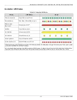
Controller LED Status

Table 12.  Controller LED Status

Mode

LED Status

Visual

Firmware download

Green blinks every 200 ms.

No application 

a)

Red, Green, Yellow blinks every 1 s.

Broken sensor 

Red permanent ON 

b)

.

Short circuit

AutoMac

Green blinks every 2 s.

No Valid Mac

Yellow permanent ON.

Un Ack Alarm

Yellow blinks every 2 s.

Normal operation

Green LED permanent ON.

Communication error

Red LED blinks every 200 ms.

a)

 While performing setpoint balancing using the VAV mobile application, the LED pattern changes from static green to red, green, yellow 

cycles (which indicates the controller is empty).
b) For troubleshooting a permanent red LED, navigate to IRM Program > On Board IO and check the UIO function block OutCase status. 

A permanent red LED will be illuminated when the OutCase status is SensorOpen (broken sensor) or SensorClose (short circuit).

Summary of Contents for CENTRA LINE MERLIN NX Series

Page 1: ... Examples 18 Networking Concepts 19 The RS485 Standard 19 Network Topologies 19 Daisy Chain 19 Spanning Tree Protocol RSTP 19 BACnet IP 20 DHCP IP Configuration 20 Static IP Configuration 20 Connect to a IP network 20 Antenna 20 Installing the Local Antenna 20 Installing the Remote Antenna 20 Remote Antenna Placement 21 BACnet MS TP VARIANT 22 Termination Resistors 22 RS 485 Bias Switches 22 BACne...

Page 2: ...ddress specific applications with ARENA NX Niagara tool Modbus and Sylk bus sub bus integration options Fig 1 Controller Part Numbers Description Table 1 ordering part number Part Number UIO SSR Sum IO Backbone Comm DIP switch BLE integrated CLMEVA75I24NM 7 5 12 IP No No CLMEVA00IB24NM 0 0 0 IP No Yes CLMEVA75IB24NM 7 5 12 IP No Yes CLMEVA75M24NM 7 5 12 MS TP Yes No CLMEVA00MB24NM 0 0 0 MS TP Yes ...

Page 3: ...o be accessible from the Internet e g to perform remote maintenance a coded VPN connection is indispensable Suitable VPN routers are available from numerous third party manufacturers in various designs for operation at 230 V or 24 V GENERAL SAFETY INSTRUCTIONS While performing any work installation mounting startup follow all instructions provided by the manufacturer and the safety instructions pr...

Page 4: ...122 F Humidity 5 to 95 RH non condensing Protection IP20 NEMA 1 Pollution Level 2 Parameter Specification Wall Modules Sensors CLCMTR40 CLCMTR40 H CLCMTR40 H CO2 CLCMTR40 CO2 CLCMTR42 CLCMTR42 H CLCMTR42 H CO2 CLCMTR42 CO2 CLCMTR71 H CLCMTR120 TR75E and CLCMTR120 H TR75 HE Parameter Specification CPU Crossover processor NXP I MRT Cortex M7 Memory Capacity 16 MB QSPI Flash 16 MB SDRAM Ethernet IP M...

Page 5: ...isters can have an address between 1 and 65534 Parameter Specification Dimension L x W x H 175 2 x 154 3 x 90 2 mm 7 x 6 x 3 1 2 in Weight 1 5 Kg 3 06 lb Mounting Fixation with bracket and shaft Parameter Specification AO Analog output Voltage 0 2 to 10 VDC direct or reverse with 3 mA to 20 mA Current 0 4 to 20 mA UI Universal input Voltage input 0 2 to 10 VDC direct or reverse Current input 0 4 t...

Page 6: ... 8 ආ ආ 5 32 5 25 ආ 9ආ 6 9 17 11 6 59ආ 87721 6 ඇN MODULES 9 32 5 62 ආ 67 7 5 6 665 ආ 5 3 ආ5 2 6 1625 17 11 6 25 02 21 7 5 1625 21 ආ3 7 51 7 5 5 ආ 5 3 ආ5 2 6 1625 DECLUTCH BUTTON RS485 MODBUS RTU 81ආ9 56 ආ13876 2873876 8 ආ ආ 5 32 5 25 ආ 9ආ 6 9 17 11 6 59ආ 87721 6 ඇN MODULES 9 32 5 62 ආ 67 7 5 6 665 ආ 5 3 ආ5 2 6 1625 17 11 6 25 02 21 1 3 6 7 25 06 73 9 5 176 21 LES 5 67 7 6 665 5 3 2 6 1625 21 1 176 ...

Page 7: ... UIO 19 IO1 Universal signal input output1 Input 0 20mA 0 10V NTC10K NTC20K RTD Output 0 10V 0 20mA 20 C Ground 21 IO2 Universal signal input output2 Input 0 20mA 0 10V NTC10K NTC20K RTD Output 0 10V 0 20mA 22 IO3 Universal signal input output3 Input 0 20mA 0 10V NTC10K NTC20K RTD Output 0 10V 0 20mA 23 C Ground 24 IO4 Universal signal input output4 Input 0 20mA 0 10V NTC10K NTC20K RTD Output 0 10...

Page 8: ...vert to their factory settings The user settings for Modbus and BLE will be erased the IP address will be reset to default and the device will enter DHCP IP configuration Pressing Service Button during Normal Operation During normal operation of the controller a short press 1 sec of the Service Button will cause a Service Pin Message BACnet WhoAmI as a Private Transfer SerialNo 130 to be sent This...

Page 9: ...rilling template provided in box The MERLIN NX IP and MSTP VAV controller s inte gral actuator does not float inside the housing there fore it should be installed with a floating mount to allow for non concentric travel which can occur with a damper shaft that are out of round and or have asymmetrical damper shaft mounts If the actuator does not allow any wobble it is likely to bind To prevent thi...

Page 10: ... reduce the rotation travel c Tighten the two mechanical end limit screws Phillips 2 screwdriver 26 5 31 lb in 3 0 3 5 Nm torque d Using the Declutch button rotate the universal shaft adapter fully clockwise e Mount the actuator to the VAV damper box and shaft f Tighten the two bolts on the centering clamp 8 mm wrench 70 lb in 8 10 Nm torque g When the actuator closes the damper rotates CCW either...

Page 11: ... sense elements and a heater The heater tends to repel dust particles via a thermophoretic effect past the heater and tends to keep most dust off the bridge structure The heat affect along with a simple filter can help to keep the dust from causing output shifts in the output of the device Although the sensor naturally repels dust some dust and contamination can still collect on the micro structur...

Page 12: ...ree Fig 12 Removing the sensor cover 2 Disconnect the electrical connector by gently pulling it away from the differential pressure sensor 3 Replace the airflow sensor Fig 13 Replace the sensor 4 Attach the electrical connector NOTE Before closing the sensor cover make sure to push the excess cable into the controller cavity The sensor cover will not snap into the controller if the cable is not tu...

Page 13: ...ring guidelines for example IEC 364 6 61 or VDE 0100 may take pre cedence over recommendations provided in these installation instructions To comply with CE requirements devices having a voltage of 50 1000 VAC or 75 1500 VDC but lacking a supply cord plug or other means for disconnecting from the power supply must have the means of dis connection incorporated in the fixed wiring This type of disco...

Page 14: ...O A KNOWN EARTH GROUND UL Listed Class 2 Transformer 100 VA 120 240 VAC 3 2 1 V0 3 2 1 V0 3 2 1 V0 COM 24 VAC Earth Ground 1 MERLIN IP MSTP CONTROLLER MERLIN IP MSTP CONTROLLER MERLIN IP MSTP CONTROLLER UL Listed Class 2 Transformer Field Device Transformer 100 VA 120 240 VAC 3 2 1 V0 AC OUT 5 4 SR IN 8 7 6 COM 24 VAC Earth Ground 1 SR1 C SR2 120 240 VAC M Power Wiring Example For One Controller P...

Page 15: ...g for the terminal blocks as follows Strip 1 2 in 13 mm insulation from the conductor Cut a single wire to 3 16 in 5 mm Insert the wire in the required terminal location and tighten the screw If two or more wires are being inserted into one terminal location twist the wires together a minimum of three turns before inserting them see Fig 15 below Cut the twisted end of the wires to 3 16 in 5 mm bef...

Page 16: ...ND MST TP VAV CONTROLLER INSTALLATION INSTRUCTIONS EN1Z 1076GE51 R0722 16 Internal Wiring Examples IP MODEL INTERNAL WIRING Fig 16 IP Model Internal Wiring MSTP MODEL INTERNAL WIRING Fig 17 MSTP Model Internal Wiring ...

Page 17: ...nnection Example Ensure correct polarity 0 to 10 VDC V Voltage Input Thermistor Resistive Input Dry contacts Digital Input Current Input 100 to 100 k e g 20 kNTC PT1000 dry contact contact open collector Ensure correct polarity logic circuit DIGITAL 0 V IO C V V IO IO C IO C IO C S External Power Supply Ensure correct polarity S S S S 0V IN IN 0V 0V IN Output Type Load 0 to 10 VDC 10 mA max 1 k 4 ...

Page 18: ...d State Relay SSR 6 UL Listed Class 2 Transformer Field Devices 100 VA 120 240 VAC 3 2 1 V0 AC OUT 5 4 SR IN 8 7 6 MERLIN IP MSTP VAV CONTROLLER COM 24 VAC Earth Ground 1 1 WHEN CONNECTING POWER TO THE MERLIN IP MSTP VAV CONTROLLERS CONNECT THE COM LEG OF THE VAC SECONDARY CIRCUIT TO A KNOWN EARTH GROUND SR1 C SR2 M M UL Listed Class 2 Transformer Field Devices 100 VA 120 240 VAC 3 2 1 V0 AC OUT 5...

Page 19: ...7 cable use only one single pair for one bus Belden 9842 or 9842NH Network Topologies Recommended cable Cat5 Cat6 Maximum distance between 2 controllers or control ler and switch should be less than 328 ft 100 meters Daisy Chain In the daisy chain connection type if any of the device in the network fails the devices next to the failed device also fail Suppose there are 10 devices in a network and ...

Page 20: ... IP address Fig 23 Static IP Configuration Refer IRM Engineering Tool User Guide for more information on how to do this Connect to a IP network MERLIN NX BACnet IP VAV controller communicates over wired IPV4 network using Ethernet connection via one of two RJ45 ports ANTENNA The MERLIN NX IP and MSTP VAV controllers have a local rubber antenna included in the packaging If the MERLIN NX IP and MSTP...

Page 21: ...ds the device it is communicating with e g WiFi Node Fig 26 Remote Antennae Placement Do not install the antenna close to the floor Fig 27 Remote Antennae Placement Keep the antenna away from devices that cause wireless interference such as other Wi Fi network and telecommunications equipment The Local antenna can be used when the IP and MSTP VAV controller is installed in a plastic cabinet enclos...

Page 22: ...aters can be used between any two devices Termination Resistors Matched terminating resistors are required at each end of a segment bus wired across and Use matched precision resistors rated W 1 80 130 Ω Ideally the value of the terminating resistors should match the rated characteristic impedance of the installed cable For example if the installed MSTP cable has a listed characteristic impedance ...

Page 23: ...ass the token The polling process includes searching for new clients with MAC addresses lying between their own MAC address and that of the next client The property maxMaster specifies the highest allowable address for master nodes The maxMaster is set to 64 by default thus guaranteeing that on a BACnet MS TP bus with for example 35 BACnet MSTP VAV controllers all of the other BACnet MSTP VAV cont...

Page 24: ...S TP Buses The controller communicates via its BACnet MS TP interface with other BACnet MS TP capable devices for example other room controllers or MS TP controllers In doing so the following considerations should be taken into account Maximum BACnet MS TP bus length L on Fig 18 See Table 7 Baud rate vs Maximum cable length on page 22 Twisted pair cable for example AWG 18 1 mm2 J Y ST Y 4 x 2 x 0 ...

Page 25: ...e responsibility of the installing commissioning person to ensure proper function NOTE Each Modbus segment will require its own line polarization and line termination Modbus Master Specifications Modbus Compliance As per the Modbus standard the controller is a conditionally compliant regular Modbus device The controller differs from an unconditionally compliant regular Modbus device in that it doe...

Page 26: ...ule must be version 1 00 3 or higher NOTE CLCMTR70 Wall Modules are not supported Sylk Bus Wiring Examples Fig 33 Sylk Wiring Topologies Table 9 Recommended max distances from controller to CLCMTR40x CLCMT42x wall modules Single twisted pair Non Shielded Stranded or Solidc Standard non twisted thermostat wire shielded or Non Shielded Stranded or Solidd 18 22 AWG 0 33 to 1mm2 24 AWG 0 20 mm2 18 24 ...

Page 27: ...oneywell Connect Mobile VAV Balancing app The BACnet instance ID range allows the discovery of additional controllers on the BACnet network For more information about VAV balancing with the HCM mobile app refer to Honeywell Connect Mobile VAV Balancing application User Guide EN2Z1086 IE67 Honeywell Connect Mobile HCM is a mobile VAV balancing application that connects to the MERLIN NX VAV controll...

Page 28: ...Status Mode Status Tx and Rx LED Status Visual BACnet Tx1 Fail OFF BACnet Tx1 Success Blinking BACnet Rx1 Fail OFF BACnet Rx1 Success Blinking Modbus Tx2 Fail OFF Modbus Tx2 Success Blinking Modbus Rx2 Fail OFF Modbus Rx2 Success Blinking Table 11 Bluetooth LED Status Mode LED Status Visual BLE disabled by user OFF BLE normal operation and connected Green permanently ON BLE enabled but not connect...

Page 29: ...manent ON Un Ack Alarm Yellow blinks every 2 s Normal operation Green LED permanent ON Communication error Red LED blinks every 200 ms a While performing setpoint balancing using the VAV mobile application the LED pattern changes from static green to red green yellow cycles which indicates the controller is empty b For troubleshooting a permanent red LED navigate to IRM Program On Board IO and che...

Page 30: ...me aux CNR d Industrie Canada applicables aux appareils radio exempts de licence L exploitation est autorisee aux deux conditions suivantes 1 l appareil ne doit pas produire de brouillage et 2 l utilisateur de l appareil doit accepter tout brouillage radioelectrique subi meme si le brouillage est susceptible d en compromettre le fonctionnement CE Statement The WLAN function for this device is rest...

Page 31: ... information on substances in articles Any supplier of an article containing a substance meeting the criteria in Article 57 and identified in accordance with Article 59 1 in a concentration above 0 1 weight by weight w w shall provide the recipient of the article with sufficient information available to the supplier to allow safe use of the article including as a minimum the name of that substance...

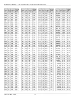
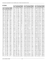
Page 32: ...ultant voltage are listed on the following pages The stated values do not include failures due to sensor failures wiring resistance or wiring failures misreadings due to a meter connected to measure resistance or voltage at the input Table 14 Accuracies of internal NTC10k Ω and NTC20k Ω sensor inputs of the controller Range Measurement error excluding sensor characteristics NTC10kΩ a NTC20k Johnso...

Page 33: ... Temp C Resistanc e KΩ Terminal voltage V 89 6 32 1124 0 432 91 4 33 1128 0 433 93 2 34 1132 0 435 95 35 1136 0 436 96 8 36 1140 0 438 98 6 37 1144 0 439 100 4 38 1148 0 441 102 2 39 1152 0 442 104 40 1155 0 443 105 8 41 1159 0 445 107 6 42 1163 0 446 109 4 43 1167 0 448 111 2 44 1171 0 449 113 45 1175 0 451 114 8 46 1179 0 452 116 6 47 1182 0 453 118 4 48 1186 0 455 120 2 49 1190 0 456 122 50 119...

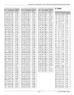
Page 34: ...95 1740 0 653 384 8 196 1744 0 655 386 6 197 1747 0 656 388 4 198 1751 0 657 390 2 199 1755 0 658 Temp F Temp C Resistanc e KΩ Terminal voltage V 392 200 1758 0 659 393 8 201 1762 0 661 395 6 202 1766 0 662 397 4 203 1769 0 663 399 2 204 1773 0 665 401 205 1777 0 666 402 8 206 1780 0 667 404 6 207 1784 0 669 406 4 208 1788 0 67 408 2 209 1791 0 671 410 210 1795 0 672 411 8 211 1799 0 674 413 6 212...

Page 35: ... 669 2 354 2311 0 849 671 355 2314 0 85 672 8 356 2318 0 852 674 6 357 2321 0 853 676 4 358 2325 0 854 678 2 359 2328 0 855 680 360 2332 0 856 681 8 361 2335 0 857 683 6 362 2339 0 859 685 4 363 2342 0 86 687 2 364 2346 0 861 689 365 2349 0 862 690 8 366 2353 0 863 692 6 367 2356 0 864 Temp F Temp C Resistanc e KΩ Terminal voltage V 694 4 368 2360 0 866 696 2 369 2363 0 867 698 370 2367 0 868 699 ...

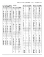
Page 36: ...1 7 722 2 299 89 6 32 7 402 2 228 91 4 33 7 098 2 159 93 2 34 6 808 2 091 95 35 6 531 2 025 96 8 36 6 267 1 962 98 6 37 6 015 1 9 100 4 38 5 775 1 84 102 2 39 5 546 1 781 104 40 5 327 1 724 105 8 41 5 117 1 669 107 6 42 4 917 1 616 109 4 43 4 726 1 564 111 2 44 4 543 1 514 113 45 4 369 1 465 114 8 46 4 202 1 418 116 6 47 4 042 1 373 118 4 48 3 889 1 329 120 2 49 3 743 1 286 122 50 3 603 1 244 123 ...

Page 37: ... 1254 190 87 8 1156 195 90 6 1066 200 93 3 984 205 96 1 909 8 210 98 9 841 9 215 101 7 779 8 220 104 4 723 225 107 2 671 230 110 0 623 3 235 112 8 579 5 240 115 6 539 4 Temp F Temp C Resistance Ω Temp F Temp C Resistance Ω 30 34 44 86 20 28 89 89 10 23 33 91 0 17 78 93 10 12 22 95 20 6 67 97 30 1 11 100 32 0 00 100 40 4 44 102 50 10 00 104 60 15 56 106 70 21 11 108 77 25 00 110 80 26 67 110 90 32 ...

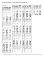
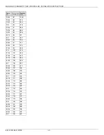
Page 38: ... KΩ Termina l voltage V 89 6 32 14 5 3 52 91 4 33 13 9 3 43 93 2 34 13 3 3 33 95 35 12 7 3 24 96 8 36 12 1 3 15 98 6 37 11 6 3 06 100 4 38 11 1 2 97 102 2 39 10 7 2 89 104 40 10 2 2 81 105 8 41 9 78 2 72 107 6 42 9 37 2 64 109 4 43 8 98 2 57 111 2 44 8 61 2 49 113 45 8 26 2 42 114 8 46 7 92 2 34 116 6 47 7 6 2 27 118 4 48 7 29 2 2 120 2 49 7 2 14 122 50 6 72 2 07 123 8 51 6 45 2 01 125 6 52 6 19 1...

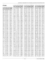
Page 39: ...641 3 2 16 77138 5 15 72911 6 8 14 68940 8 6 13 65209 10 4 12 61703 12 2 11 58405 14 10 55304 15 8 9 52385 17 6 8 49638 19 4 7 47050 21 2 6 44613 23 5 42317 24 8 4 40151 26 6 3 38110 28 4 2 36184 30 2 1 34366 32 0 32651 33 8 1 31031 35 6 2 29500 37 4 3 28054 39 2 4 26687 41 5 25395 42 8 6 24172 44 6 7 23016 46 4 8 21921 48 2 9 20885 50 10 19903 51 8 11 18973 53 6 12 18092 55 4 13 17257 57 2 14 164...

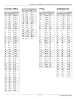
Page 40: ...06 6 97 741 208 4 98 720 210 2 99 699 212 100 678 213 8 101 659 215 6 102 640 217 4 103 622 219 2 104 604 221 105 587 222 8 106 571 224 6 107 555 226 4 108 539 228 2 109 524 230 110 510 231 8 111 496 233 6 112 482 235 4 113 469 237 2 114 457 239 115 444 240 8 116 432 242 6 117 421 244 4 118 410 246 2 119 399 248 120 388 249 8 121 378 251 6 122 368 253 4 123 359 255 2 124 350 257 125 341 Temp F Tem...

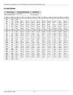
Page 41: ...56 5 961 9 967 3 972 7 978 2 983 6 989 1 994 5 32 0 1000 1005 5 1011 1016 5 1022 1027 6 1033 1 1038 7 1044 3 1049 9 50 10 1055 5 1061 1 1066 8 1072 4 1078 1 1083 8 1089 5 1095 2 1100 9 1106 6 68 20 1112 4 1118 1 1123 9 1129 7 1135 5 1141 3 1147 1 1153 1158 8 1164 7 86 30 1170 6 1176 5 1182 4 1188 3 1194 2 1200 2 1206 1 1212 1 1218 1 1224 1 104 40 1230 1 1236 1 1242 2 1248 2 1254 3 1260 4 1266 5 12...

Page 42: ...090 7 1095 3 1100 1104 6 1109 3 1114 1118 7 1123 4 1128 1 1132 9 86 30 1137 6 1142 4 1147 1 1151 9 1156 7 1161 5 1166 3 1171 2 1176 1180 9 104 40 1185 7 1190 6 1195 5 1200 4 1205 3 1210 2 1215 1 1220 1 1225 1230 122 50 1235 1240 1245 1250 1255 1260 1 1265 1 1270 2 1275 3 1280 3 140 60 1285 5 1290 6 1295 7 1300 8 1306 1311 1 1316 3 1321 5 1326 7 1331 9 158 70 1337 2 1342 4 1347 6 1352 9 1358 2 1363...

Page 43: ...to change without notice RELATED TECHNICAL LITERATURE Table 16 Related Technical Literature Title Reference MERLIN NX IP Product Datasheet EN0Z1073 GE51 MERLIN NX MSTP Product Datasheet EN0Z1072 GE51 MERLIN NX IP and MSTP Mounting instructions EN1Z1074GE51 MERLIN NX Migration Guide EN2Z1061 GE51 Honeywell Connect Mobile VAV Balancing application User Guide EN2Z1086 IE67 IRM Engineering Guide EN2B0...

Reviews: