EAGLEHAWK CONTROLLER – INSTALLATION & COMMISSIONING INSTRUCTIONS
EN1Z-1005GE51 R0216
6
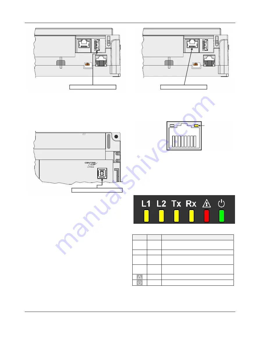
USB 2.0 Host Interface
J1
J8
EN
D
BI
AS
MI
D
Fig. 5. USB 2.0 Host interface
USB 2.0 Device Interface
All models of the EAGLEHAWK controller are equipped with a
USB 2.0 Device Interface at the front. This interface is for
connection to COACH
AX
and web browsers, or 3
rd
-party touch
panels.
USB 2.0 Device Interface
Fig. 6. USB 2.0 Device Interface
A standard USB type-B connector can be inserted into this
USB 2.0 Device Interface. This USB 2.0 Device Interface is
the recommended interface for connection to COACH
AX
.
Ethernet / RJ45 Socket
The EAGLEHAWK controller is equipped with an Ethernet /
RJ45 socket featuring one LED.
J1
J8
Ethernet / RJ45 socket
EN
D
BI
AS
MI
D
Fig. 7. Ethernet / RJ45 socket
This Ethernet / RJ45 socket is a 10/100-Mbaud Ethernet
interface permitting communication (as per IEEEC 802.3) on
any supported IP network, e.g.: BACnet (IP), FOX, etc.
LINK/ACT.
Fig. 8. Ethernet / RJ45 socket
NOTE:
The Ethernet / RJ45 socket is usually earth-
grounded. For additional information on earth
grounding, see also “Appendix 1: Earth Grounding”
on pg. 30.
LEDs
The EAGLEHAWK controller features the following LEDs:
Fig. 9. EAGLEHAWK controller LEDs
Table 4. EAGLEHAWK controller LEDs
symbol
color
function, description
L1 yellow
Heartbeat LED indicating platform is
running
L2
yellow LED indicating that station is starting up
Tx yellow
RS485-1 status LED indicating trans-
mission of communication signals.
Rx yellow
RS485-1 status LED indicating reception
of communication signals.
!
red
status LED indicating hardware problems
green power
LED
See also section “EAGLEHAWK Controller Troubleshooting”
on page 28 for a detailed description of the behaviors of the
LEDs and their meanings.


