GB
Honeywell GmbH
4
MU0H-1264 GE23 R0818
4
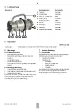
Scope of Delivery
5
Options
6
Assembly
6.1 Installation Guidelines
•
Note flow direction
•
Use both handles when assembling on hydrant /
standpipe
•
Ensure that parts are free of dirt
•
Store in a clean and dry place
•
These armatures need to be maintained regularly
6.2 Assembly instructions
1.
Thoroughly flush hydrant / standpipe
2.
Check that backflow preventer connections are clean
3.
Assemble backflow preventer
Position backflow preventer and, using both handles, rotate it
and the counter coupling on the hydrant/standpipe to connect
Note flow direction (indicated by arrow)
7
Maintenance
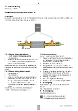
7.1 Inspection
The backflow preventer must undergo regular visual
inspections every 3 months at the latest. The following must
be checked:
•
State of the coupling
•
Dirt accumulation
–
Stone trap
–
Dust and fall protection
–
Drainage holes
–
Interior workings
If dirt has accumulated, clean with clear water without the
addition of detergents.
If any parts are damaged carry out a maintenance.
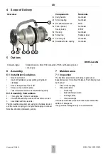
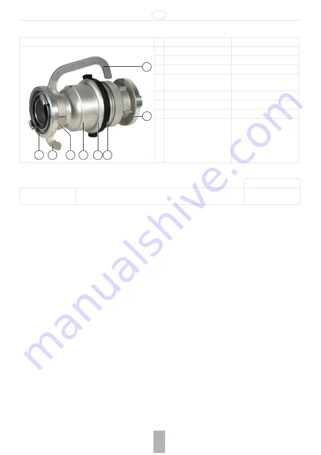
Overview
Components
Materials
1
Carry handle
Aluminium
2
Storz coupling
Aluminium
3
Dirt and fall protection
NBR
4
Piston (inside)
Seals (inside)
Aluminium
EPDM
5
Housing
Aluminium
6
Stone trap
Stainless steel
7
Counter grip
Aluminium
8
Rotatable Storz coupling
Aluminium
1
2
3
4
5
7
8
6
BFW112-65A
Connection type:
Standard version, Storz 75-B connection, PN16, with handle grip and
counter grip
•

