


BENDIX/KING
KI 208, KI 209
Rev 4, Aug 2002
IM 006-00140-0004
Page 1-3
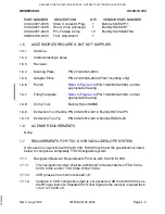
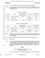
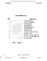
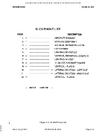
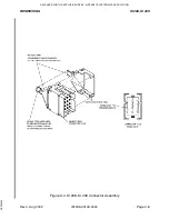
PART NUMBER
DESCRIPTION
QTY
VENDOR PART NUMBER
030-02227-0005
Shell, Connector Plug
1
Burndy SMS12P-1
030-02227-0009
Hood, Conn (2 pieces)
1
Burndy SMS12H1
030-02227-0023
Pin, Female Crimp
12
Burndy SC20M-6TK6
088-00706-0000
Tool, Adjustment
1
1.5
ACCESSORIES REQUIRED, BUT NOT SUPPLIED
1.5.1
Antenna.
1.5.2
Interconnecting Cables.
1.5.3
Receiver.
1.5.4
Mooring Plate
P/N 073-00044-0001.
1.5.5
Adapter Plate
P/N 073-00045-0000 (Front mounting only).
(P/N 155-05235-0000) or other
appropriate drawing.
(P/N 155-05235-0000) or other
appropriate drawing.
1.5.8
Crimp Tool
Burndy Hytool M8ND
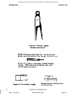
1.5.9
Extraction Tool Handle P/N 005-02012-0012, Burndy RXT20-4P3
1.5.10
Extraction Tool Tip
P/N 005-02012-0013, Burndy RXK20-25
1.6
LICENSE REQUIREMENTS
None.
1.7
REQUIREMENTS FOR TSO’D VOR/ILS/GLIDESLOPE SYSTEM
Units used in conjunction with the KI 208, KI 209 must meet the specifications listed
below to comprise a completely TSO’d navigation system.
1.7.1
Navigation Receiver Requirements For Use with KI 208, KI 209.
1.7.1.1
The navigation receiver shall be authorized to the standards of TSO C40a,
C40b, C40c, and/or TSO C36c, C36d, C36e.
1.7.1.2
VOR phase error shall not exceed 1.5°.
1.7.1.3
Variation in VOR composite output to not exceed ±3 dB from 0.500 Vrms as
the RF input level of a Standard VOR Test Signal to the receiver is varied from
10 uV to 10,000 uV.
RELEASED FOR THE EXCLUSIVE USE BY: AIRCRAFT ELECTRONICS ASSOCIATION
UP536434