

BENDIX/KING
TABLE OF CONTENTS
KI 208, KI 209
Rev 4, Aug 2002
IM 006-00140-0004
TOC-1
SECTION I
GENERAL INFORMATION
Paragraph
Page
............................................................................................. 1-1
............................................................................. 1-1
......................................................................... 1-1
1.4 Units and Accessories Supplied
.............................................................. 1-2
1.5 Accessories Required, But Not Supplied
................................................. 1-3
............................................................................. 1-3
1.7 Requirements for TSO’d VOR/ ILS/ Glideslope System
.......................... 1-3
LIST OF TABLES
Table
Page
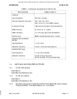
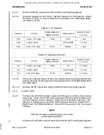
1-1 Technical Characteristics KI 208, KI 209
................................................. 1-1
SECTION II
INSTALLATION
Paragraph
Page
.................................................................................................... 2-1
2.2 Unpacking and Inspecting Equipment
..................................................... 2-1
2.3 Installation KI 208, KI 209
....................................................................... 2-1
2.4 Post Installation Checkout
....................................................................... 2-2
LIST OF TABLES
Table
Page
.......................................................................................... 2-3
............................................................................... 2-3
LIST OF ILLUSTRATIONS
Figure
Page
..................................................................................... 2-5
..................................................................................... 2-6
.......................................................................................... 2-7
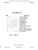
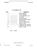
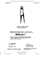
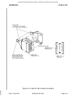
2-4 KI 208, KI 209 Connector Assembly
....................................................... 2-8
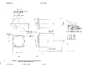
2-5 KI 208, KI 209 Outline and Mounting
..... (Dwg 155-05235-0000) ........... 2-9
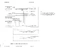
2-6 KI 208, KI 209 Typical Interconnect
....... .............................................. 2-11
2-7 KI 208 Non-TSO’d System Interconnect
. (Dwg 155-01223-0000) ......... 2-13
2-8 KI 209 System Interconnect
.................... (Dwg 155-01241-0000) ......... 2-15
RELEASED FOR THE EXCLUSIVE USE BY: AIRCRAFT ELECTRONICS ASSOCIATION
UP536434