


BENDIX/KING
KI 208, KI 209
Rev 4, Aug 2002
IM 006-00140-0004
Page 2-3
2.4.1.7
Remove VOR RF signal and verify that NAV warning flag appears.
2.4.1.8
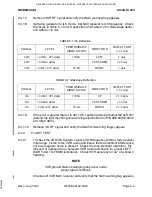
Set ramp generator to ILS mode. Set NAV receiver to ILS frequency. Check
the levels in Table 2-1 for ILS deflection and Table 2-2 for Glideslope deflec-
tion within ±1/2 dot.
2.4.1.9
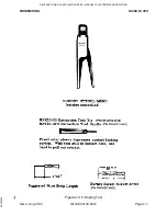
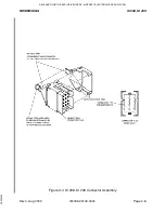
If the error is greater than ±1/2 dot, LOC centering may be readjusted by R227
(behind top right mounting screw) using adjustment tool P/N 088-00706-0000
at 0 dB (0 ddm).
2.4.1.10
Remove ILS RF signal and verify that NAV/GS warning flag(s) appear.
2.4.2
FLIGHT TEST
2.4.2.1
To check the VOR/ILS System, select a VOR frequency within a forty nautical
mile range. Listen to the VOR audio and insure that no electrical interference
such as magneto noise is present. Check the tone identifier operation. Fly
inbound or outbound on a selected VOR radial and check for proper LEFT-
RIGHT and TO-FROM indications. Check VOR accuracy for ±5° of a known
heading.
NOTE
VOR ground station scalloping may occur under
weak signal conditions.
Channel off VOR NAV receiver and verify that the NAV warning flag appears.
TABLE 2-1 ILS Deflection
SIGNAL
LEVEL
PREDOMINATE
MODULATION
DIRECTION
DEFLECTION
(±1/2 dot)
LOC
+4 dB (+.093 ddm)
150 Hz
LEFT
3 dots
LOC
+0 dB (0 ddm)
CENTERED
±1/2 dot
LOC
-4 dB (-.093 ddm)
90 Hz
RIGHT
3 dots
TABLE 2-2 Glideslope Deflection
SIGNAL
LEVEL
PREDOMINATE
MODULATION
DIRECTION
DEFLECTION
(±1/2 dot)
GS
+2 dB (>.091 ddm)
150 Hz
UP
2 1/2 dots
GS
+0 dB (0 ddm)
CENTERED
±1/2 dot
GS
-2 dB (.091 ddm)
90 Hz
DOWN
2 1/2 dots
RELEASED FOR THE EXCLUSIVE USE BY: AIRCRAFT ELECTRONICS ASSOCIATION
UP536434