


Bendix/King by Honeywell
KMA 30 Audio Panel and Intercom System
Installation and Operator’s Manual
200-890-5464
Page 2-9
Rev. 1, Aug. 2012
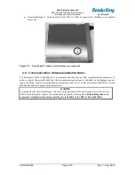
revision), Chapter 3, for information on proper antenna installation techniques. The marker beacon an-
tenna must be mounted on the bottom of the aircraft.
2.6.2
External Marker Lights
For installations that require external marker beacon lights, there are three outputs that can drive 12-Volt
lamps only. The external output lamps are driven high (typ7.0 VDC
4.0 VDC unloaded, at MAX
brightness) when active. Maximum source current per lamp is 125 mA. Voltage varies with photocell
dimming.
2.6.3
Middle Marker Sense
A Middle Marker Sense output signal is available from the PMA8000 to certain flight control systems.
This function will not operate during the test mode. This output will go to +4.5 VDC (
1.0 VDC) when a
valid Middle Marker signal is received. This output is J1, pin 39.
2.7 Adjustments
The KMA 30 is factory adjusted to accommodate the typical requirements for most aircraft configurations.
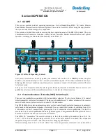
There are three adjustments in the top cover that allow the installer to tailor the specific functions.
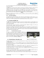
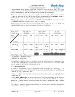
Figure 2-4- KMA 30 Adjustments, top cover
Speaker Volume- Turn adjustment clockwise to increase cabin speaker output.
Marker Beacon Volume, turn adjustment counterclockwise to increase marker beacon audio
level.
TEL volume, turn adjustment Clockwise to increase the incoming telephone audio.
ANN VOL Function Mode Annunciation Volume – controls the level of the to access voice an-
nunciations contained in the unit. (Top cover must be removed).
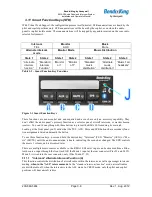
Front
of unit
NOTE:
If top cover is removed
for ANY reason, you
MUST replace the cover
screws with the proper
length, otherwise damage
will result.
Shorter Screw