background image

6    

sensing.honeywell.com

Installation and Technical Manual for the 


Summing In-Line Amplifier, Order Code AA919

ISSUE A


008-0749-00

3.4  |  Output Scaling


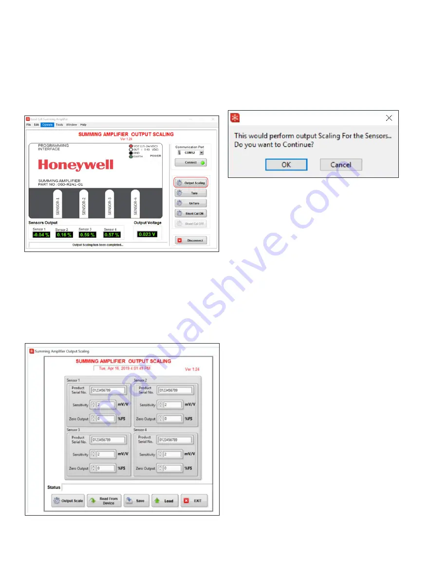
1.  Click on the Output Scaling button on the application 

interface that should now be active. 

Figure 3.4a. Output Scaling Option

2.  The user interface reads the default configuration values 

from the Summing In-Line Amplifier and displays them.

3.  Modify desired values based on calibration sheets provid-

ed by the sensor manufacturers. Fields available include 
product serial number, sensitivity in mV/V, and zero output 
of the sensor from the calibration sheet. Zero output has to 
be entered as % of FS.

Figure 3.4b Output Scaling User Interface

4.  Click on the Output Scale button to apply the changes 

back to the amplifier. The application interface asks for 
verification first.

Figure 3.4c. Verify Output Scaling Changes

5.  Click OK to continue.

Note:
• 

The Sensivity should be within the Range of 1.5 mV/V-12 
mV/V. You will see a warning if the value is out of range.

• 

Zero Output should be within ± 10 % of FS. You will see a 
warning if the value is out of range.

Summary of Contents for AA919

Page 1: ... injury Failure to comply with these instructions could result in death or serious injury Sensing and Internet of Things m AVERTISSEMENT MAUVAIS USAGE DE LA DOCUMENTATION Les informations complètes d installation d utilisation et d entretien sont fournies avec les instructions accompagnant chaque produit L inobservation de ces instructions risque d entraîner des blessures graves voire mortelles m ...

Page 2: ...ation of Software and Drivers 3 3 1 1 System Requirements 3 3 1 2 Loading Software and Device Drivers 3 3 2 Making the Connections 5 3 2 1 Connect Amplifier to Power 5 3 2 2 Connect the Sensors 5 3 3 Connect Amplifier to PC and Launch Desktop Application 5 3 3 1 Connect Mini USB cable 5 3 4 Output Scaling 6 3 5 Save Configuration 7 3 6 Load Configuration 7 3 7 Tare and UnTare 8 3 8 Shunt Calibrati...

Page 3: ...e Device Configuring Output Scaling of the Sensor s Preload Tare Shunt Calibration excitation voltage for the transducer and converts the millivolt signal from the transducer to a 0 10 Vdc amplified signal The Summing In Line Amplifier features include auto excitation voltages programmable gain settings and a wide adjustment range on the Span and offset value 1 2 Product Specifications Power Requi...

Page 4: ...tions Rear Side The rear view below shows the power input cable as well as the USB mini connector for Programming interface to connect the Summing In Line Amplifier to host PC Figure 2 2 External Connections Cable and Mini USB The Summing In Line Amplifier can be powered from a 15 24V DC power supply The power cable used for the Summing In Line Amplifier is shielded 4 core cable There are 4 conduc...

Page 5: ...ystem Windows 7 or Windows 10 32 64 bits The screen must support and be set for a resolution of 800 x 600 or higher 3 1 2 Loading Software and Device Drivers 1 Download the required Summing In Line Amplifier Soft ware and Device Drivers from the following URL https sensing honeywell com test measurement products summing amplifiers aa919 2 Unzip the downloaded file to a location on your computer or...

Page 6: ...ion Install Completes 7 Install the Future Technology Devices International FTDI Combined Driver Model CDM drivers Click on the Extract button Figure 3 1 2e FTDI CDM Driver Installation 8 After extraction click Next to continue with the Device Driver installation Figure 3 1 2f Device Driver Welcome Screen 9 Accept the agreement by selecting the radio button and click Next Figure 3 1 2g Device Driv...

Page 7: ... be connected As sensors are connected accompanying port LEDs on the front of the amplifier will glow green 3 3 Connect Amplifier to PC and Launch Desktop Application 3 3 1 Connect Mini USB cable 1 Connect the smaller end of the provided Mini USB cable to the port on the rear of the Summing In Line Amplifier as shown in 2 2 Then connect the larger end of the mini USB cable to a USB port on the com...

Page 8: ...vid ed by the sensor manufacturers Fields available include product serial number sensitivity in mV V and zero output of the sensor from the calibration sheet Zero output has to be entered as of FS Figure 3 4b Output Scaling User Interface 4 Click on the Output Scale button to apply the changes back to the amplifier The application interface asks for verification first Figure 3 4c Verify Output Sc...

Page 9: ...ure 3 6b Load Configuration Option 3 Click on the Output Scale button to apply the settings to the amplifier Figure 3 6c Apply Settings to Device 4 Verify that the settings were loaded into the amplifier by clicking Read From Device Figure 3 6d Read from Device Option 5 Exit Output Scaling by clicking on Exit Figure 3 6e Exit Output Scaling Option 3 5 Save Configuration 1 To save the configuration...

Page 10: ...zeroing the preload on setup Click the Tare button to load Zero Value to the amplifier Note Tare limit is 30 of FS When the preload of load on the amplifier is more than 30 of FS Tare command will show an error Figure 3 7a Tare Option 2 Click Yes to continue with the Tare function Figure 3 7b Tare Validation 3 The Output Voltage is now set close to zero and the values are saved to flash memory on ...

Page 11: ...itivity is connected to the amplifier the output of the amplifier will saturate to 70 of full scale during the shunt calibration Table 3 8a Shunt calibration Output vs Bridge resis tance Sensitivity Output of the Summing In Line Amplifier under shunt calibration for any other values of the bridge resistance and sensitivity can be calculated using this equation Shunt Cal On Output 0 000004286 Bridg...

Page 12: ...imit Crossed Because the example shows 50 of load applied the device would pop up a warning message 4 WARNING ERROR MESSAGES 4 1 Output Scaling The Sensitivity should be within the Range of 1 5mV V 12mV V The user interface will pop up a warning when it is out of range Figure 4 1 Sensivity Out of Range If the entered value is more than 12 a default value of 12 mV V will be used If the entered valu...

Page 13: ...four LEDs will glow green 1 When sensors are not conencted to an amplifier port the LED for that port will glow red instead of green Likewise when the amplifier is connected to a PC laptop with the desktop application running the sensor displays will also glow green or red Figure 5 Sensor LED and Desktop Interface In this example you see that sensors 3 and 4 are not connected and glowing red on th...

Page 14: ...ical Manual for the Summing In Line Amplifier Order Code AA919 ISSUE A 008 0749 00 Notices and Trademarks While this information is presented in good faith and believed to be accurate Honeywell disclaims the implied warranties of merchantability and fitness for a particular purpose and makes no express warranties except as may be stated in its written agreement with and for its customers In no eve...

Reviews: