Sensing and Internet of Things
11
Installation and Technical Manual for the
Summing In-Line Amplifier, Order Code AA919
ISSUE A
008-0749-00
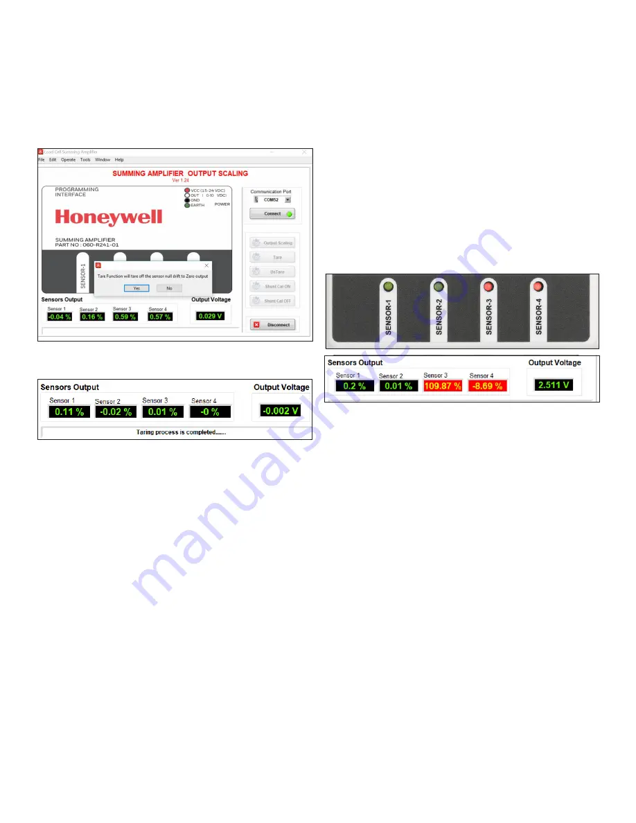
Here is an example showing a successful Tare using 25 % load
on Sensor 1.
Figure 4.2b. Successful Tare
The Output also shows appropriate value in a successful Tare..
5 | DIAGNOSTIC FEATURES
The amplifier’s sensor LED indicators glow red or green de-
pending on whether a sensor is connected to the amplifier port.
Under normal operating conditions with four sensors connect-
ed to the amplifier, all four LEDs will glow green.
1. When sensors are not conencted to an amplifier port, the
LED for that port will glow red instead of green. Likewise
when the amplifier is connected to a PC/laptop with the
desktop application running, the sensor displays will also
glow green or red.
Figure 5. Sensor LED and Desktop Interface
In this example you see that sensors 3 and 4 are not
connected and glowing red on the amplifier and the user
interface.
2. A red indicator can also mean the sensor is faulty, a bridge
is open, or shorted out.
3. A red indicator also indicates a sensor is loaded more than
110 % of FS.
Example: When the load on an individual sensor is more
than 110 % of FS, the LED will blink red to indicate poten-
tial overload of the sensor.


