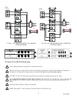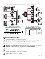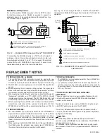
FIG. 10 — ML7984 WIRING WITH SERIES 90 MECHANICAL 135
!
(SLIDEWIRE) CONTROLLERS
FIG. 10A — ML7984 WIRING WITH COMMON
TRANSFORMER, INDIVIDUAL CONTROLLERS
FIG. 10B — ML7984 WITH INDIVIDUAL
TRANSFORMERS, COMMON CONTROLLER
RESISTOR SELECTION CHART
NO. OF
ACTUATORS
RESISTOR
VALUE
1
2
3
4
RESISTOR NOT REQ'D.
133 OHM
68.1 OHM
45.3 OHM
ALL RESISTORS
1/4 WATT
1% METAL FILM
5
For Figures 10A and 10B the following apply:
Power supply provides overload protection and disconnect means.
Allow up to 0.5 amps for each device. Actuators and controller can share same transformer providing the VA rating of the
transformer is not exceeded and proper phasing is observed.
Do not mix a.c. and d.c. power sources.
Do not mix M984/6 or Modutrol Motors with the ML7984 in the same circuitry.
Use configuration DIP switches to select device functions:
Direct acting function (actuator stem moves upwards with
signal increase) or Reverse acting function (actuator stem moves downwards with signal increase).
Turn power off before setting the DIP switches. For common transformer and common controller application, please consult
the factory.
For Figure 10A Only:
Maximum resistance per control circuit of 280
!
.
For Figure 10B Only:
Use Resistor Kit part #272822.
1
2
3
4
5
7
6
7
95C-10939-4
4
7
1
L1
L2
T5
T6
28 Vdc
OR
3
2 ML7984
3
2 ML7984
3
2 ML7984
T6
T6
T6
T5
T5
T5
B
B
B
R
R
R
W
W
W
24 Vac
R
R
R
R
W
W
W
W
B
B
B
MODULATING
LIMIT
6
SINGLE
SOURCE
1
L1
L2
T5
T6
28 Vdc
OR
T6
T5
B
R
W
R
W
B
SINGLE
SOURCE
2
2
3
2 ML7984
3
2 ML7984
3
2 ML7984
7
T6
T5
B
R
W
T6
T5
B
R
W
1
L1
L2
1
L1
L2
OR
OR
T5
T6
28 Vdc
28 Vdc
2
24 Vac
24 Vac
24 Vac
T5
T6
FUNCTION
DIP SWITCH CONFIGURATION
On (1)
Off (0)
1
2
3
4
1001
Mechanical Series 90
Direct Acting
1011
Mechanical Series 90
Reverse Acting
On (1)
Off (0)
1
2
3
4

