background image


33 


Honeywell 30 Series IP Cameras User Guide 


G.711 provides good sound quality and requires about 64Kbps. Select pcmu (μ-Law) 

or pcma (A-Law) mode. 


G.726 is a speech codec standard covering voice transmission at rates of 16, 24, 32, 

and 40kbit/s. 

After you complete the settings on this page, click 

SAVE 

to enable the settings. 

Configuring IR Control Settings 

Go to 

Setup 

 Camera Setup 

 IR Control

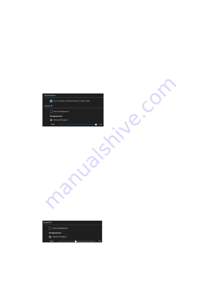
On this page, you can turn on the IR illuminator and adjust the luminance of IR lights. 

Figure 39 IR Control Settings 


IR Illuminators 

Turn on built-in IR illuminator in night mode

: Check to turn on the camera’s onboard 

IR illuminator when the camera detects low light condition and enters the night mode. 

Smart IR 

Anti-overexposure

: Check to automatically adjust the shutter speed, Gain and IRIS 

through algorithm of the firmware to avoid over-exposure in the night mode. 


Note:  

The IRIS control only applies to HC30W45R2/HC30WB5R2/HC30WE5R2 

motorized focus/zoom cameras. 

IR adjustment

: Adjust the luminance of IR lights. 

Figure 40 Smart IR 


Manual IR adjust

: Check it to control the luminance of IR lights manually. To increase 

the luminance of IR lights, drag the slider to the right; to decrease the luminance of IR 

lights, drag the slider to the left. 

Summary of Contents for 30 Series

Page 1: ...Honeywell 30 Series IP Cameras HC30W42R3 HC30W45R3 HC30W45R2 HC30WB2R1 HC30WB5R1 HC30WB5R2 HC30WE2R3 HC30WE5R3 HC30WE5R2 HC30WF5R1 HC30W25R3 HC30W25R3 12V User Guide ...

Page 2: ...l characters in password Add HLC Add Pixel Calculator Modify HTTPS Add Certificate Request and upload files Modify Motion detection intrusion detection people detection Add audio settings Add audio detection settings Add audio detection event settings Delete remote log server Modify Version screenshot Add mount type V2 A 06 2019 Modify the Focus section and the Configuring Audio Detection V3 A 09 ...

Page 3: ...es to the camera at the same time List of Symbols The following is a list of symbols that may appear on the camera Symbol Explanation The WEEE symbol This symbol indicates that when the end user wishes to discard this product it must be sent to separate collection facilities for recovery and recycling By separating this product from other household type waste the volume of waste sent to incinerato...

Page 4: ...tobiological safety according to IEC EN 62471 risk group 1 General Data Protection Regulation Please be aware that this product can store personal data Personal data is protected by the General Data Protection Regulation 2016 679 in Europe and therefore the owners of personal data have obtained certain rights thanks to this regulation We strongly advise you to be fully aware of these owner data su...

Page 5: ...eiver Connect the equipment into an outlet on a circuit different from that to which the receiver is connected Consult the dealer or an experienced radio TV technician for help Note Changes or modifications not expressly approved by the party responsible for compliance could void the user s authority to operate the equipment Canadian Compliance Statement This Class B digital apparatus complies wit...

Page 6: ... 92 1 HC30W25R3 12V Screw Lead 7439 92 1 Solder paste D3 D11 Lead 7439 92 1 Wafer Passivation_Glass D3 D11 Lead 7439 92 1 Smd Diode Body D19 D20 Lead 7439 92 1 BLACK BODY D14 Lead 7439 92 1 GPP COMMUTATING DIODE CORE Lead 7439 92 1 High lead tin paste D1 D15 Lead 7439 92 1 Safety Instructions Before installing or operating the unit read and follow all instructions After installation retain the saf...

Page 7: ...ified service personnel 8 REPLACEMENT PARTS When replacement parts are required be sure the service technician has used replacement parts specified by the manufacturer or have the same characteristics as the original part Unauthorized substitutions may result in fire electric shock or other hazards Using replacement parts or accessories other than the original manufacturers may invalidate the warr...

Page 8: ...Camera 7 Upgrading the Camera s Firmware 8 Accessing the Camera from a Web Browser 9 4 Using the Main Page 10 Logging in to the Camera via the Web Client 10 Before You Begin 10 Logging in to the Camera 10 Using the Main Page 13 System Menu 14 Stream Profile 14 Camera Name 14 Live View Tool Bar 15 Language 15 User Account 15 Fisheye Main Page 16 Fisheye Layout 17 5 Configuring Camera 24 Configuring...

Page 9: ...ng Focus 37 Configuring Privacy Mask 39 Pixel Calculator Fisheye Model Only 40 6 Configuring Network 41 Configuring Network General Settings 41 Configuring Streaming Protocols 44 Configuring DDNS Settings 47 Configuring QoS Settings 47 Configuring SNMP Settings 49 Configuring HTTPS Settings 50 Configuring IEEE 802 1X Settings 52 7 Configuring Video Analytics 54 Configuring Motion Detection Setting...

Page 10: ...enance Settings 77 Upgrading Firmware 77 Rebooting the Camera 78 Restoring the Camera 79 Importing Exporting Files 79 Configuring User Accounts Settings 82 Account Management 83 Configuring Access List Settings 83 General Settings 84 Filter 84 Administrator IP address 85 10 Viewing System Info 86 Log 86 Version 87 11 Troubleshooting 88 Troubleshooting for Dynamic Intra Frame Period 88 Troubleshoot...

Page 11: ...iv HC30WE2R3 HC30WE5R3 96 HC30WF5R1 97 HC30W25R3 HC30W25R3 12V 98 ...

Page 12: ... One Panoramic View 19 Figure 25 One Regional View 19 Figure 26 Two Panoramic Views 20 Figure 27 One Original Three Regional Views 21 Figure 28 Regional Window Selection 21 Figure 29 Four Regional Views 22 Figure 30 One Original and Eight Regional Views 23 Figure 31 General Settings 24 Figure 32 Mode Tab 1 27 Figure 33 Mode Tab 2 27 Figure 34 Mode Tab 3 28 Figure 35 Video Stream Settings 29 Figure...

Page 13: ... 63 Figure 74 Action 63 Figure 75 Add Server 64 Figure 76 Server Type Email 65 Figure 77 Server Type HTTP 65 Figure 78 Add Media 66 Figure 79 Media Type Video Clip 67 Figure 80 Event Settings Examples 68 Figure 81 No SD Card 70 Figure 82 SD Card Onboard 70 Figure 83 SD Card Format 71 Figure 84 SD Card Control 71 Figure 85 Search the Records 72 Figure 86 Search Results 72 Figure 87 Play Search Resu...

Page 14: ... Controls 15 Table 2 Fisheye Layout 17 Table 3 Video Orientation 26 Table 4 Stream and Frame Size Matrix 28 Table 5 Compatible SD Card 69 Table 7 Troubleshooting for Dynamic I Frame Period 89 Table 8 Troubleshooting for Common Issues 90 ...

Page 15: ...mera remotely from a web browser and how to update a camera s firmware Chapter 3 Using the Main Page describes how to log in to a camera and introduce the main page Chapter 4 Configuring Camera describes camera configurations Chapter 5 Configuring Network describes network configurations Chapter 6 Configuring Video Analytics describes video analytics configurations Chapter 7 Configuring Storage de...

Page 16: ...age while ensuring maximum video quality All the cameras are True Day Night with intelligent IR capability providing up to 165 ft 50 m of illumination in low light and nighttime scenes Also all the cameras support WDR function at up to 120 dB Each camera comes with configurable motion detection and camera tamper detection and supports up to 5 user defined privacy mask areas In addition to a 12 VDC...

Page 17: ...ort required Up to 10 connections Compatible with the following network protocols IPv4 IPv6 TCP IP HTTP HTTPS UPnP RTSP RTP RTCP IGMP CIFS SMB SMTP DHCP NTP DNS DDNS CoS QoS SNMP 802 1X UDP ICMP ARP TLS Network Management Camera configuration and management via Ethernet Device management via Internet or client PC User Management Each user belongs to a specific group Different user rights for each ...

Page 18: ...Web Browser page 9 Installing the UnifiedTool To get the installation package of Unified Tool Go to https mywebtech honeywell com and login Go to Download Center Video IP Cameras Camera Discovery Tools Utilities Honeywell Unified Tool Download and unzip the installation package of Unified Tool to your computer Copy the installation package of Unified Tool from the CD along with the package of the ...

Page 19: ...ure is displayed Figure 2 Select Installation Folder 3 Follow the on screen instructions to configure settings and click Next The following figure is displayed Figure 3 Confirm Installation 4 Click Next When the installation is completed click Close A shortcut of Unified Tool will be displayed on your desktop ...

Page 20: ...uage from the drop down list of Language Currently only English is supported 2 Check Don t show the splash window on startup and this page can be skipped next time If you want to check the splash window again click as shown in Figure 6 and select the checkbox of Show the splash page on startup 3 Click CONTINUE It will scan devices in the network automatically Figure 5 Scanning the Network ...

Page 21: ...ew IP Address to a Camera The current IP address of a camera appears in the IP ADDRESS column of the devices list You can assign a new static IP address to the camera Select the target device s as shown in Figure 6 click and the following figure is displayed Figure 7 IP Assignment Configure IP Address Setting To obtain IP address subnet mask and default gateway settings automatically check DHCP ...

Page 22: ...ver Address Configure the DNS server address and click APPLY UpgradingtheCamera sFirmware Before using your camera make sure you have the latest firmware installed You can upgrade a single camera or multiple cameras at the same time Select the Maintenance tab from the left pane as shown in Figure 6 Select target device s and click The following window is displayed Figure 8 Firmware Upgrade The dev...

Page 23: ...ide Figure 9 Firmware Upgrade 2 3 Click APPLY You can check the progress status in the device list Accessing the Camera from a Web Browser To access the camera from a web browser click next to the IP address of the device as shown in Figure 6 ...

Page 24: ...llowing conditions are met The camera is properly connected to the network The camera s IP address and the PC s IP address are in the same network segment If there is a router set the corresponding gateway and subnet mask A network connection has been established To check this ping the camera s IP address Enter ping IP address Logging in to the Camera Logging in via Internet Explorer 1 Type the ca...

Page 25: ...curity Certificate Problem For how to resolve the security certificate problem see Export CA Certificate on page 81 3 Setup a new password according to the password requirements at the first login Click SAVE The password cannot be blank Figure 11 Setup a New Password 4 Enter the user name as admin and newly created password Click LOGIN ...

Page 26: ...ens Logging in Via Google Chrome 1 Type the camera s IP address in the address bar of Google Chrome and press Enter on the keyboard For example if your camera s IP address is 192 168 1 108 you would type https 192 168 1 108 Note Chrome 71 or later is supported for H 264 video Chrome is not supported for H 265 video 2 The following window is displayed Click Advanced Figure 13 Safety Problem 3 The f...

Page 27: ...see Export CA Certificate on page 81 4 Setup a new password according to the password requirements at the first login Click SAVE The password cannot be blank Figure 15 Setup a New Password 5 Enter the user name as admin and newly created password Click LOGIN Figure 16 Login Page Using the Main Page ...

Page 28: ...he corresponding tab Stream Profile In the Stream Profile list select Main Stream Sub Stream or Third Stream to set the stream profile Main Stream Delivers high definition video for real time monitoring recording and storage Uses the most bandwidth Sub Stream Delivers low standard definition video typically for remote monitoring in lower network bandwidth environments Third Stream Delivers low def...

Page 29: ... zoom the image scroll the mouse wheel This function is not applicable in the Chrome browser Click to record the video clip in MP4 file format and save it to your computer You can play the video clip by VLC player Click the button again to stop recording When you exit the web browser video recording stops accordingly If you run the Internet Explorer as administrator and this is the first time you ...

Page 30: ...To configure the user account click SETTINGS For details see Configuring User Accounts Settings on page 82 To log out the current account click LOG OUT Fisheye Main Page Click on the right of the Fisheye main page to access the Fisheye panel Figure 20 Fisheye Main Page ...

Page 31: ...s and to manipulate the details within the following types of layout are provided Figure 22 Fisheye Layout Table 2 Fisheye Layout Layout Display Mode Description 1O One original view 1P One panoramic view 1R One regional view 2P Two panoramic views 1P2R One panoramic and two regional views Wall mount 1O3R One original and three regional views 4R Four regional views ...

Page 32: ...e facial features of people passing through the area This layout is especially adequate for taking an overview glimpse of the surveillance area when mounted on the ceiling Figure 23 One Original View One Panoramic View With the image correction algorithms in firmware the hemispheric image is transformed into a rectilinear stripe in the 1P display mode You can use the PTZ panel or simply use mouse ...

Page 33: ...own the left mouse button and you can drag the view in all directions Figure 25 One Regional View One Panoramic and Two Regional Views This layout provides access to two regional views and the reference to their relative positions on a panoramic view This layout is available only when you select the Wall mount type see the Video Settings on page 25 The operations of this layout is similar to the o...

Page 34: ...e operations of the One Original and Three Regional Views see One Original and Three Regional on page 20 One Original and Three Regional Views This layout provides access to multiple live view sections within the hemisphere and the reference to their relative positions on an Original circular view The FOV Field of View indicators 1 3 interact with your current operation when you zoom in out or mov...

Page 35: ...egional window in the original window Figure 28 Regional Window Selection Note After you click the live image the mouse wheel becomes the zoom in out tool Four Regional Views This layout control and look and feel are identical to that as described in the One Original and Three Regional Views except that the Original circular view is absent from this mode ...

Page 36: ...egional Views except that the quad view windows consecutively rotate in correspondence to the change of view area in one window Note The zoom in out and tilt control is not available in this mode One Original and Eight Regional Views This layout control and look and feel are identical to that as described in the One Original and Three Regional Views ...

Page 37: ... Original and Eight Regional Views Note If you change the position of a view in hemisphere e g the 3 window you will lose the configuration change when switching to another display mode The live view window does not automatically save your view section layout ...

Page 38: ...Settings page 32 Configuring IR Control Settings page 33 Configuring Image Settings page 34 Configuring Exposure Settings page 35 Configuring Focus page 37 Configuring Privacy Mask page 39 Pixel Calculator Fisheye Model Only page 40 Configuring General Settings Go to Setup Camera Setup General Settings On this page you can configure the general video settings and day night settings Figure 31 Gener...

Page 39: ...l Only The camera provides 3 Mount types Ceiling Wall and Floor Ceiling The Ceiling mount type automatically delivers upside down images The Ceiling mode supports the following Display modes 1O 1P 1R 2P 1O3R 4R 4R PRO and 1O8R Wall The Wall mount type applies to the monitoring of long side to side surveillance areas such as when mounted on a wall facing a corridor Different Mount types have differ...

Page 40: ...s Switch to B W in night mode Check to enable the camera to automatically switch to Black White during night mode IR cut filter Auto mode The Day Night Exposure Profile will not be available if Auto mode is selected The camera automatically removes the filter by judging the level of ambient light Note Select auto mode will disable profile of exposure settings Day mode In day mode the camera always...

Page 41: ...de will clear the following settings privacy mask exposure widow motion and focus window Figure 32 Mode Tab 1 4 Megapixel Max Resolution 2688x1520 Select it and the maximum resolution will be 2688x1520 The aspect ratio will be 16 9 This mode applies to HC30W45R3 HC30W45R2 HC30WB5R1 HC30WB5R2 HC30WE5R3 HC30WE5R2 HC30W25R3 HC30W25R3 12V cameras see Figure 32 5 Megapixel Max Resolution 2560x1920 Sele...

Page 42: ... 640x360 640x360 HC30W45R2 5MP 2560x1920 2048x1536 1600x1200 1280x960 800x600 704x480 640x4 80 800x600 704x48 0 640x480 640x480 70 4x480 HC30WB2R1 1920 1080 1600x904 1360x768 12 80x720 640x360 1280x720 640x3 60 640x360 HC30WB5R1 4MP 2688x1520 1920x1080 1600x904 1 280x720 640x360 1280x720 640x3 60 640x360 HC30WB5R1 5MP 2560x1920 2048x1536 1600x1200 1280x960 800x600 704x480 640x4 80 800x600 704x48 0...

Page 43: ...0 704x480 640x4 80 800x600 704x48 0 640x480 640x480 70 4x480 Figure 35 Video Stream Settings Frame Size You can set different video resolutions for different viewing devices For example you can configure a smaller frame size and lower bit rate for remote viewing on mobile phones and a larger video size and a higher bit rate for live viewing on web browsers or recording the stream to an NVR A large...

Page 44: ... the previous I or P frames for redundant image information Smart FPS In a static scene the algorithm puts old frames in queue when no motions occur in scene When motions occur the encoding returns to normal to deliver real time streaming By queuing the old frames from a static scene both the computing efforts and the size of P frames are reduced It is beneficial for keeping up with the frame rate...

Page 45: ...of the ROI areas On the contrary the farther the slider to the left the higher the image quality of the non interested area In this way you can set up an ROI window as a privacy mask by covering a protected area using an ROI window while the rest of the screen becomes the non interested area You can configure the non interested area to have a high image quality or vice versa Bit Rate Control Const...

Page 46: ...increase when noises are produced with electrical gains Configuring Audio Settings Go to Setup Camera Setup Audio Note HC30WF5R1 HC30W25R3 12V HC30W25R3 supports this function Figure 37 Audio Settings HC30W25R3 Figure 38 Audio Settings HC30WF5R1 HC30W25R3 12V Mute Check to disable audio transmission from the network cameras to all clients Microphone source Select Internal or External from the drop...

Page 47: ...nators Turn on built in IR illuminator in night mode Check to turn on the camera s onboard IR illuminator when the camera detects low light condition and enters the night mode Smart IR Anti overexposure Check to automatically adjust the shutter speed Gain and IRIS through algorithm of the firmware to avoid over exposure in the night mode Note The IRIS control only applies to HC30W45R2 HC30WB5R2 HC...

Page 48: ...b configure special situations for image settings Figure 41 Image Settings White Balance Adjust the value for the best color temperature Auto Select it and the camera will automatically adjust the color temperature Fixed current Select it and the camera will use current color temperature value Manual You can manually tune the color temperature by dragging the R Gain and B Gain slider Image Adjustm...

Page 49: ...s smog fog or smoke 3D Noise Reduction Drag the slider to adjust the reduction strength from low to high Note 3D Noise Reduction is mostly applied in low light conditions In a low light condition with fast moving objects trails of after images may occur You can select a lower strength level All changes made to image settings are directly shown on screen To recall the original settings without inco...

Page 50: ...om the inclusive window An exposure value will then be calculated out of the remaining of the inclusive window Center This option will automatically add an inclusive window in the middle of the window and give the necessary light compensation HLC Highlight Compensation Firmware detects strong light sources and compensates on affected spots to enhance the overall image quality For example the HLC h...

Page 51: ...hnique that enhances the image quality by adjusting the gamma value to brighten dark areas True WDR is a sensor based technology A True WDR CCTV can produce images with an extremely wide dynamic range The WDR image sensor can capture several images with short and long exposures then combining them into a single frame Configuring Focus Focus here refers to the Remote Focus applicable to the cameras...

Page 52: ...sition on screen 2 It is recommended to Reset to the default back focus position of the sensor board 3 You can check Fully opened iris default to increase the iris size for a better focus adjustment result 4 Check Fully opened iris or Full range scan buttons Full range scan Check it to run a full range scan about 30 to 80 seconds through the camera s entire focal length If it is not checked the au...

Page 53: ...iew window This function will not take effect if you set the focus window on a distant background Configuring Privacy Mask On this page you can block out sensitive view areas to address privacy concerns Go to Setup Camera Setup Privacy Mask To configure privacy masks for Non PTZ models 1 Click NEW to add a new privacy mask window on the video screen 2 Use 4 mouse clicks to create a new mask window...

Page 54: ...xel calculator window 2 Move it to an area of your interest 3 Place the cursor to the right bottom corner of window and drag the corner to change the size of window 4 The calculated numbers will be listed at the lower screen You can see if the current setting fulfills your requests for the number of pixels For instance for recognizing the faces of persons passing through a location A facial recogn...

Page 55: ...onfiguring QoS Settings page 47 Configuring SNMP Settings page 49 Configuring HTTPS Settings page 50 Configuring IEEE 802 1X Settings page 52 Configuring Network General Settings This section describes how to configure a wired network connection for the camera Figure 48 Network Type LAN Acquire IP address automatically Check to obtain an available dynamic IP address assigned by the DHCP server eve...

Page 56: ...ondary WINS server The secondary WINS server that maintains the database of computer names and IP addresses Enable UPnP presentation Check to enable UPnP presentation for your camera so that whenever a camera is presented to the LAN the shortcuts to connected cameras will be listed in Network and Sharing Center You can click the shortcut to link to the web browser Note Click SAVE to enable the set...

Page 57: ...advertisements and be assigned with a link local IPv6 address accordingly IPv6 Information Click to obtain the IPv6 information as shown below Figure 50 IPv6 Information If your IPv6 settings are successful the IPv6 address list will be listed in the pop up window Follow the steps below to link to an IPv6 address 1 Open your web browser 2 Enter the link global or link local IPv6 address in the add...

Page 58: ... following blanks will be displayed for you to enter the corresponding information Figure 51 Manually Setup IP Address Configuring Streaming Protocols Go to Setup Network Setup Streaming Protocols Figure 52 Streaming Protocols HTTP To utilize HTTP authentication make sure that you have set a password for the camera first For more information see Configuring User Accounts Settings on page 82 Authen...

Page 59: ...tion against unauthorized access Access name for main stream sub stream third stream The camera supports multiple streams simultaneously The access name is used to differentiate the streaming source If you want to use an RTSP player to access the camera you must set the video mode to H 264 or H 265 and use the following RTSP URL command to request transmission of the streaming data rtsp ip address...

Page 60: ...ion Figure 54 Multicast Settings Always multicast Check to enable multicast for video streams Multicast group address Enter the Multicast group address Multicast video port Multicast RTCP video port The ports can be changed to values between 1025 and 65535 The multicast video port must be an even number and the multicast RTCP video port number is the multicast video port number plus one and thus i...

Page 61: ...provider from the drop down list Camera name Enter the camera name of your dynamic domain account User name Enter the user name of your dynamic domain account Password Enter the password of your dynamic domain account Configuring QoS Settings Go to Setup Network Setup Qos Quality of Service QoS is a network security mechanism It fixes problems with network delays and jams For network service the q...

Page 62: ...andle video packets first Note A VLAN Switch 802 1p is required Web browsing may fail if the CoS setting is incorrect The Class of Service technologies do not guarantee a level of service in terms of bandwidth and delivery time they offer a best effort Users can think of CoS as coarsely grained traffic control and QoS as finely grained traffic control Although CoS is simple to manage it lacks scal...

Page 63: ...e SNMP consists of the following three key components Manager Network management station NMS a server which executes applications that monitor and control managed devices Agent A network management software module on a managed device which transfers the status of managed devices to the NMS Managed device A network node in a managed network For example routers switches bridges hubs computer hosts p...

Page 64: ...NMPv3 which contains cryptographic security a higher security level Security name Choose Read Write or Read Only and enter the community name according to your NMS settings Authentication type Select MD5 or SHA as the authentication method Authentication password Enter the password for authentication at least 8 characters Encryption password Enter a password for encryption at least 8 characters Co...

Page 65: ... can fill in certificate information and the certificate request file can be exported to the certificate issuing authority for signing and then being imported to camera Figure 60 Certificate Request Enter the information of Country State or province Locality Organization and Organization unit Click CREATE Click EXPORT to export the certificate request to your local computer After you get the signi...

Page 66: ...e file format cert format Supported Key format PEM format Configuring IEEE 802 1X Settings Go to Setup Network Setup 802 1X IEEE802 1X is the access control and authentication protocol for local and metropolitan area networks It uses a port based network access control protocol to restrict unauthorized user and or device access to the LAN The network devices intermediary switch access point hub an...

Page 67: ...gurations EAP TLS Select EAP PEAP or EAP TLS as the EAP method Enter your ID and password issued by the CA and then upload related certificate s 3 When all settings are complete move the camera to the protected LAN by connecting it to an 802 1x enabled switch The devices will then start the authentication automatically ...

Page 68: ...Settings Go to Setup Video Analytics Motion Detection Two sets of motion detection settings are available In Normal Light Mode tab configure normal situations for motion detection settings In Profile Mode tab configure special situations for motion detection settings Night Mode Check Enable to apply these settings at and select this mode to apply the settings at night Schedule Mode Check Enable to...

Page 69: ...he object size slider to change the minimum size of item to trigger an alarm An object size box will appear in the center of screen for your reference in semi transparent red An intruding object must be larger than the Object size to trigger an alarm Change the object size according to the live view c To delete a window click on the right of the window name d Define the sensitivity to moving objec...

Page 70: ...ection Settings Intrusion Detection Note Fisheye model HC30WF5R1 doesn t support intrusion detection function The intrusion detection function detects people motions in customized windows If a people motion is detected the frame of the customized window will become flashing red ...

Page 71: ...by clicking four corner points on the target area You can change the shape of the detection area by dragging the corner points 4 Click SAVE to enable the settings 5 Select Enable motion detection to enable this function People Detection Note Fisheye model HC30WF5R1 doesn t support people detection function The people detection function can detect and trace people motions in customized windows If a...

Page 72: ...n change the shape of the detection area by dragging the corner points 4 Click SAVE to enable the settings 5 Check Enable motion detection to enable this function Note Only one kind of motion detection motion detection intrusion detection or people detection can be enabled at a time Configuring Tampering Detection Settings Go to Setup Video Analytics Tampering Detection This section explains how t...

Page 73: ... how sensitive the tamper detection setting is The lower the threshold value the easier the detection is triggered You can configure Tampering Detection as a trigger element to the proactive event configurations in Video Analytics Event settings Trigger For example when the camera is tampered with camera can be configured to send the pre and post event video clips to a networked storage device For...

Page 74: ...el slider to a preferred location on the left slide bar 3 Check Enable audio detection and click SAVE Note The volume numbers 0 100 on the left side of wave diagram does not represent decibel dB Sound intensity level has already been mapped to preset values You can however use the real world inputs at your installation site that are shown on the wave diagram to configure an alarm level To configur...

Page 75: ...r apart from the detected sound level To configure and enable this feature you must not configure video stream 1 into Motion JPEG If an external microphone input is connected and recording of audio stream is preferred audio stream is transmitted between camera and viewer recording station along with stream 1 Configuring Event Settings Go to Setup Video Analytics Event Settings This section describ...

Page 76: ...executed first Detect next motion detection or digital input after x seconds Enter the duration in seconds to pause motion detection after a motion is detected This can prevent event related actions to take place too frequently Schedule Specify the time period during which the event trigger will take effect Select the days of a week and the time in a day in 24 hr time format for the event triggeri...

Page 77: ...999 minutes can be set System boot This option triggers the camera when the power to the camera is disconnected and re connected Recording notification This option allows the camera to trigger when the recording disk is full or when recording starts to overwrite older data Camera tampering detection This option allows the camera to trigger when the camera detects that is being tampered with To ena...

Page 78: ...k the View button for network storage a file directory window will prompt for you to view recorded data on network storage Create folders by date time and hour automatically If you select this item the system will automatically create folders by the date when video footages are stored onto the network storage Add Server Click Add server to open the server setting window You can specify where the n...

Page 79: ... to 25 You can also manually set another port If your SMTP server requires a secure connection SSL select This server requires a secure connection To verify if the email settings are correctly configured click TEST The result will be shown in a pop up window If successful you will also receive an email indicating the result Click SAVE SERVER to enable the settings After you configure the first eve...

Page 80: ... Select the item to display the detailed configuration options You can configure either one or all of them Figure 78 Add Media Media type Snapshot Select to send snapshots when a trigger is activated Media name Enter a name for the media setting Source Select to take snapshots from any of the video streams Send pre event image s The camera has a buffer to temporarily hold data up to a certain limi...

Page 81: ...he maximum recording duration in seconds The duration can be up to 10 seconds For example if pre event recording is set to five seconds and the maximum duration is set to ten seconds the camera continues to record for another 4 seconds after a trigger is activated File name prefix Enter the text that will be appended to the front of the file name Maximum file size Specify the maximum file size all...

Page 82: ...t Settings Examples When the Event Status is ON the event configuration above is triggered by motion detection the camera will automatically send snapshots via e mail If you want to stop the event trigger click on the ON button to turn it to OFF status or click DELETE to remove the event setting To remove a server setting from the list select a server name and click DELETE You can only delete a se...

Page 83: ...s and implement SD card control See the following table for compatible SD Card Table 5 Compatible SD Card SD Card Brand Model Size Cameras Cameras Sandisk microSDXC UHS I Card 256G Toshiba microSDXC UHS I Card 256G Samsung microSDXC UHS I Card 256G Toshiba microSDXC UHS I Card 128G Sony Smart SD micro SDXC 64G Sony Ultra microSDHC UHS I 48MB s 64G Samsung microSDXC UHS I Card 64G Micron microSDXC ...

Page 84: ...Do not modify or change the folder names in the SD card That may result in camera malfunctions If you want to use the SD card in another camera format the SD card in another camera first For how to format the SD card see SD Card Format on page 70 SD Card Status This tab shows the status and reserved space of your SD card Remember to format the SD card when using it for the first time see SD Card F...

Page 85: ... to retain a file For example if you enter 7 days the recorded files will be stored on the SD card for 7 days Maximum duration for keeping file Enter a day number for maximum duration for keeping files Click SAVE to enable settings Content Management Go to Setup Storage Setup Content Management This section describes how to manage the content of recorded videos on the camera You can search and vie...

Page 86: ... want to search for contents created at a specific point in time Click SEARCH and the recorded data corresponding to the search criteria will be listed in Search Results tab Search Results The following is an example of search results To sort the search results click each column header Figure 86 Search Results Play Click on a search result and a Play window will be displayed for immediate review o...

Page 87: ... which will not be deleted during cyclic recording You can click again to unlock the selections Remove Select the desired search results then click REMOVE to delete the files Recording Settings Go to Setup Storage Setup Recording Settings This section describes how to configure the recording settings for the camera Figure 88 Recording Settings SD Test Insert the SD card and click here to test Note...

Page 88: ... the I frame data during normal monitoring thus effectively saves bandwidths and storage space Note To enable adaptive recording make sure you ve set up the trigger source such as Motion Detection or Manual Trigger For more information see Configuring Event Settings on page 61 When there is no alarm trigger JPEG mode record 1 frame per second H 264 mode record the I frame only When the I frame per...

Page 89: ...e size for each recording footage File name prefix Enter the text that will be appended to the front of the file name If you want to enable recording notification click Event to configure event triggering settings For more information see Configuring Event Settings on page 61 When completed select Enable this recording Click SAVE to enable the setting and click CLOSE to exit this page When the sys...

Page 90: ...guring System General Settings Go to Setup System Setup General Settings This section explains how to configure the basic settings for the camera such as the host name and system time Figure 91 Configuring System General Settings Camera Name Enter a name for the camera The text will be displayed at the top of the main page Turn off system status indicator If you don t want others to notice the net...

Page 91: ...time manually The date and time formats are yyyy mm dd and hh mm ss Automatic The Network Time Protocol is a protocol which synchronizes computer clocks by periodically querying an NTP Server NTP server Assign the IP address or domain name of the time server Leaving the text box blank connects the camera to the default time servers The precondition is that the camera must have the access to the In...

Page 92: ...e camera is upgraded If the upgrade is successful the Reboot system now This connection will close message will be displayed After that re access the camera If an SD card is inserted to the camera wait for the SD card formatting to complete If the power is disconnected during firmware upgrade or if there is unknown reason causing abnormal LED status and a Restore cannot recover normal working cond...

Page 93: ...osition parameters If none of the options is selected all settings will be restored to factory default Click RESTORE and the camera will be rebooted After it is completed the live video page will be displayed in your browser If the connection fails after rebooting manually enter the IP address of the camera in the address field to resume the connection Importing Exporting Files Export Update dayli...

Page 94: ...d ends at 2 00 a m on the first Sunday in November Figure 94 Set the Start and End Time of DST Export Language File The camera supports the following languages English German Spanish French Italian Japanese Portuguese Russian and traditional Chinese If your language is not listed perform the following steps to customize the camera language Taking the English language file for example 1 Click EXPOR...

Page 95: ... double click the certificate The Certificate window opens 3 In the Certificate window on the General tab click Install Certificate to open the Certificate Import Wizard 4 Click Next to continue 5 Click Place all certificates in the following store and click Browse Click Trusted Root Certification Authorities and click OK 6 Click Next and then click Finish to close the Certificate Import Wizard A ...

Page 96: ...configuration file The password must be the same as the password of the configuration file you set for exporting or the uploading will be failed For example if you set a password A for a configuration file A and you set a password B for a configuration file B When you want to upload the configuration file B you must use the password B 2 Click CHOOSE FILE to locate the configuration file and then c...

Page 97: ...w user account Click ADD to enable the setting The privilege levels are listed below Role Privilege Administrator Full control Viewer Live Language Access rights are sorted by user privilege Administrator Operator and Viewer Only administrators can access the Configuration page Viewers can only access the main page for live viewing To change a user s access rights or delete a user account 1 Select...

Page 98: ...e clients whose IP addresses are on the Access List below will not be allowed to access the camera and the others can Click ADD and you can add a rule to the following Access List Single This rule allows the user to add an IP address to the Allowed Denied List Network This rule allows the user to assign a network address and corresponding subnet mask to the Allow Deny List The address and network ...

Page 99: ... IP Cameras User Guide Administrator IP address Always allow the IP address to access this device Check it and add the Administrator s IP address in this field to make sure the Administrator can always connect to the device ...

Page 100: ...ys the system events in a chronological order The system log is stored in the camera s buffer area and will be deleted after the camera is rebooted Figure 98 System Log Access Log Access log displays the access time and IP address of all viewers including operators and administrators in a chronological order The access log is stored in the camera s buffer area and will be deleted after the camera ...

Page 101: ...87 Honeywell 30 Series IP Cameras User Guide Figure 99 Access Log Version Go to Setup Information Version On the Version page you can view the software version Figure 100 Version ...

Page 102: ...eb page go to Setup Camera Setup Video STREAM Video settings for main stream Video settings for sub stream Video settings for third stream and uncheck Dynamic I Frame period as shown in the following illustration Figure 101 Video Settings for Dynamic I Frame Period Otherwise the following problems may be observed on NVR s and VMS es when an operator is doing actions e g play live videos play back ...

Page 103: ...Maxpro VMS HEN 3 HEN 4 DVM ADPRO Live view Need to wait for at most 10 seconds to display live video Not support Smart Codec Uncheck Dynamic I Frame period 2x and above forward playback Playback speed is not accurate OK Reverse playback Playback speed is not accurate Playback from a specific time The playback will start from at most 10 seconds later of the specific time OK Playback video with even...

Page 104: ... web client Ensure that your browser s security settings allow ActiveX controls Ensure that you have a valid network setup and that you are using the correct login user name and password Water leaking into camera housing Do not unscrew the air tight hole Power supply is unstable Use of a UPS power supply is strongly recommended The page of changing password is lost Change the password of the camer...

Page 105: ...CHAPTER 91 Honeywell 30 Series IP Cameras User Guide 11 APPENDIX Specifications HC30W42R3 HC30W45R3 ...

Page 106: ...92 Honeywell 30 Series IP Cameras User Guide HC30W45R2 ...

Page 107: ...93 Honeywell 30 Series IP Cameras User Guide HC30WB5R2 ...

Page 108: ...94 Honeywell 30 Series IP Cameras User Guide HC30WB2R1 HC30WB5R1 ...

Page 109: ...95 Honeywell 30 Series IP Cameras User Guide HC30WE5R2 ...

Page 110: ...96 Honeywell 30 Series IP Cameras User Guide HC30WE2R3 HC30WE5R3 ...

Page 111: ...97 Honeywell 30 Series IP Cameras User Guide HC30WF5R1 ...

Page 112: ...98 Honeywell 30 Series IP Cameras User Guide HC30W25R3 HC30W25R3 12V ...

Page 113: ...paña Tel 34 902 667 800 Honeywell Building Technologies Security Россия и СНГ 121059 Moscow UI Kiev 7 Russia Tel 7 495 797 93 71 Honeywell Building Technologies Security Asia Pacific Building 1 555 Huanke Road Zhang Jiang Hi Tech Park Pudong New Area Shanghai 201203 China Tel 400 840 2233 Honeywell Building Technologies Security and Fire ASEAN Honeywell International Sdn Bhd Level 25 UOA Corp Towe...

Reviews: