Top Cover Assembly Kit Instruction, continued
62-86-33-25
Page 3 of 5
Step
Action
4
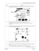
Disconnect three wire connectors from the edge connectors (Phv, Pan and Pcpu) on the power
distribution PWA. See Figure.
Power Distribution PWA
Connectors for
Transformer cables
Phv Pan Pcpu
Ppwr Pmtr
J4
5
Disconnect wire connector from Ppwr connector on power distribution PWA.
Remove black and gray wire leads at pins 5 and 6 of the connector. Mark as necessary for
reassembly.
6
Disconnect cable from P5 connector on the main PWA. Disconnect ribbon cable from P4 connector
on the Main PWA (if present). See figure.
Main CPU
PWA
P5
P4
7
Cut any cable ties to free the transformer wires from other cables, if necessary.
8
Disconnect the green wire of the transformer from the chassis ground connection on the actuator
case.
If adding the local display and keypad function to the actuator, go to step 10.
Procedure continued on next page
⇒


