Top Cover Assembly Kit Instruction, continued
Page 4 of 5
62-86-33-25
Step
Action
9
If replacing the top cover assembly –
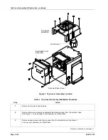
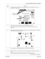
Disconnect the wire connector from J4 of the power distribution PWA. See figure in step 4.
10
Remove top cover assembly from actuator.
11
Install the new top cover assembly by first connecting the wire connector to J4 on the power
distribution PWA. Make sure that other end of the cable is connected to J2 on display PWA located
in the top cover.
12
Connect the ribbon cable from the display PWA to P4 on the main PWA. See figure in step 6.
Connect the 3-pin cable (wire colors orange, orange, gray) from the transformer to P5 on the main
PWA. See figure in step 6.
13
Identify the primary wire leads of the replacement transformer (black, red and white) and alter as
necessary:
For 120 Vac power input – Cut red wire and crimp with wire nut.
For 240 Vac power input – Cut black wire and crimp with wire nut.
Insert the unaltered wire into pin 3 of the Ppwr connector and the white wire into pin 4 of the
connector.
14
Connect the transformer primary green wire to the chassis ground on the actuator case.
15
Insert the black and gray wires (removed in step 5) into pin 5 (black) and pin 6 (gray) of the Ppwr
connector.
16
Connect three wire connectors (of the replacement transformer) to the edge connectors (Phv, Pan
and Pcpu) on the power distribution PWA. See Figure in Step 4.
17
Use cable ties to bundle cables together.
18
Install new gaskets and then replace top cover and extended cover. Secure covers to actuator with
screws.
19
Reapply AC power to the actuator.
20
Verify actuator configuration and check for correct display and keypad operation.
21
Return actuator to service.

