background image

GB

2

MU0H-1155GE23 R0319

1

Safety Guidelines

1.

Follow the installation instructions.

2.

Use the appliance

according to its intended use

in good condition

with due regard to safety and risk of danger.

3.

Note that the appliance is exclusively for use in the 
applications detailed in these installation instructions. 
Any other use will not be considered to comply with 
requirements and would invalidate the warranty.

4.

Please take note that any assembly, commissioning, 
servicing and adjustment work may only be carried out 
by authorized persons.

5.

Immediately rectify any malfunctions which may 
influence safety.

2

Description of Function

Spring loaded check valves have a moving seal disc which is 
lifted off the seat by a greater or lesser amount depending on 
the flow rate through the valve. If the flow falls towards zero, 
then the spring pushes the disc back onto the seat and seals 
the waterway.
To ensure continuing correct function it is recommended that 
check valves be regularly checked and maintained (as 
specified in EN 1717).
The filter insert is divided into two parts. In the „filtering“ 
position, only the lower, larger section is used for filtering. The 
small upper section does not come in contact with unfiltered 
water. An oscillating flap integrated in the sieve prevents the 
deposition of dirt particles on the upper part of the filter. When 
the ball valve is opened for reverse rinsing, then the whole 
filter insert is pushed downwards until the water supply to the 
outer side of the main filter is stopped. Simultaneously, the 
water flow is opened to the upper part of the filter. The water 
needed for cleaning the filter passes through the upper filter 
section, then the rotating impeller with jets and the main filter 
from inside to outside, i.e. the filter is reverse rinsed with 
filtered water. The filter automatically switches back to the 
operating position when the ball valve is closed again. 
Spring loaded pressure reducing valves operate by means of 
a force equalising system. The force of a diaphragm operates 
against the force of an adjustment spring. If the outlet 
pressure and therefore diaphragm force fall because water is 
drawn, the then greater force of the spring causes the valve 
to open. The outlet pressure then increases until the forces 
between the diaphragm and the spring are equal again. 
The inlet pressure has no influence in either opening or 
closing of the valve. Because of this, inlet pressure fluctuation 
does not influence the outlet pressure, thus providing inlet 
pressure balancing.

3

Technical Data

4

Scope of Delivery

Check valve:

Media

Medium: Drinking 

water

Connections/Sizes

Connection sizes: 

DN65 - DN100 

Pressure values

Max. operating pressure: 

2.0 - 16.0 bar

Outlet pressure: 

1.5 - 7.5 bar

Inlet pressure: 

max. 16 bar

Nominal pressure: 

PN16 

Min. pressure drop: 

1.0 bar

Opening pressure check 
valve: 

ca. 0.05 bar

Operating temperatures

Max. operating temperature 
medium: 

65°C (max. operating 
pressure 6.0 bar) 

Specifications

Installation position: 

Horizontal with filter bowl 
downwards 

Flanges on inlet and outlet:  Flanges PN16 acc. to DIN 

86021 / ISO 7005-2, EN 
1092-2 

Components

Materials

1

Housing and housing end 
casing with flanges

Grey cast iron coated with 
PA (polyamide)

Not depicted components:

Check valve insert

Stainless steel

Test and drain plugs

Stainless steel

Screws and nuts

Stainless steel

Disc

Stainless steel

Spring

Stainless steel

Lip seal ring

EPDM

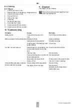
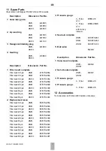
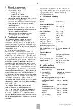
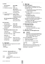
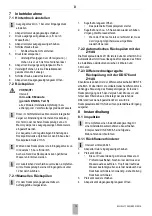
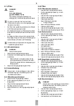
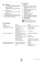
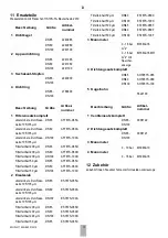
Summary of Contents for HS10S FA Series

Page 1: ...R32344916 001 HS10S FA Installation instructions Einbauanleitung Keep instructions for later use Water station Anleitung zum sp teren Gebrauch aufbewahren Wasserstation...

Page 2: ...ater needed for cleaning the filter passes through the upper filter section then the rotating impeller with jets and the main filter from inside to outside i e the filter is reverse rinsed with filter...

Page 3: ...harge connection at the filter and the sewage piping e g drain connection with syphon has to be 56mm at least To do this there are 3 options 1 Discharge into floor drain 2 Drain into open container 3...

Page 4: ...ter approx 3 5 seconds Repeat procedure three times If the filter is extremely dirty the procedure may have to be repeated additional times 7 2 2Automatic reverse rinsing with the Z11AS The automated...

Page 5: ...l 8 Screw filter bowl in place 9 Slowly open shut off valve on inlet 10 Slowly open shut off valve on outlet 8 2 4Replace filter mesh 1 Close shut off valve on inlet 2 Release pressure on outlet side...

Page 6: ...s escaping from the spring bonnet Diaphragm is faulty Replace diaphragm Spring bonnet not screwed flush Retighten the screws O ring forgotten in the diaphragm piston during assembly Insert O ring Too...

Page 7: ...65C Filter mesh 50 m DN80 AF78TS 080C Filter mesh 50 m DN100 AF78TS 100C 2 Replacement sieve Filter mesh 100 m DN65 ES78TS 065A Filter mesh 100 m DN80 ES78TS 080A Filter mesh 100 m DN100 ES78TS 100A F...

Page 8: ...eren Filter ge ffnet Das f r die Filterreinigung ben tigte Wasser durchstr mt den oberen Filterbereich den rotierenden Impeller und anschlie end den unteren Filterbereich von innen nach au en d h die...

Page 9: ...ablaufs am Filter und der Abwasserableitung z B Trichter mit Syphon mindestens 56mm betragen Dazu gibt es 3 M glichkeiten 1 Ablauf frei in vorhandenen Bodenablauf 2 Ablauf in offenen Beh lter 3 Ablauf...

Page 10: ...sp len gegebenenfalls ein Auffanggef untergestellen 1 Kugelhahn langsam ffnen Das patentierte R cksp lsystem startet 2 Kugelhahn nach ca 3 5 Sekunden wieder schlie en Vorgang drei Mal wiederholen Wenn...

Page 11: ...ausgangsseitig langsam ffnen 8 2 2Filter 8 2 3Filtereinsatz ersetzen 1 Absperrarmatur eingangsseitig schlie en 2 Druck ausgangsseitig ablassen z B durch Wasserhahn 3 Absperrarmatur ausgangsseitig sch...

Page 12: ...rgung siehe Kapitel 4 Lieferumfang Die rtlichen Vorschriften zur korrekten Abfallverwertung entsorgung beachten 10 Fehlersuche Problem Ursache Abhilfe Schlagende Ger usche Druckminderer zu gro dimensi...

Page 13: ...lterfeinheit 50 m DN80 AF78TS 080C Filterfeinheit 50 m DN100 AF78TS 100C 2 Ersatzsieb untere obere Durchlass weite 105 135 m DN65 ES78TS 065A untere obere Durchlass weite 105 135 m DN80 ES78TS 080A un...

Page 14: ...261 810 Fax 49 6261 81309 Manufactured for and on behalf of the Pittway S rl La Pi ce 4 1180 Rolle Switzerland by its Authorised Representative Ademco 1 GmbH MU0H 1155GE23 R0319 Subject to change 2019...

Page 15: ...Assembly 3 7 Start up 4 8 Maintenance 4 9 Disposal 6 10 Troubleshooting 6 11 Spare Parts 7 12 Accessories 7 D 1 Sicherheitshinweise 8 2 Funktionsbeschreibung 8 3 Technische Daten 8 4 Lieferumfang 8 5...

Page 16: ...16 MU0H 1155GE23 R0319 7 min 200mm 4 8 7 6 5 120l 2 1 3 min 250mm min 56mm min 56mm min DN70 4 11 10 5 8 6 7 1 5 2Nm 9 12Nm 9 12Nm 4 5 6 7 1 2 2 3 6 7 2 1 8 2 3 8 2 4 6 3 7 1 8 1 1 4...

Page 17: ...MU0H 1155GE23 R0319 17 4 5 7 6 4 5 6 8 2 6 11 11 8 3 1 11 6 5 8 7 7 8 8 8 8 8 8 8 9 8 8 8 5 8 6 8 8 7 9 8 7 8 11 10 10 11 11 11 11 12 11 11 13 1 2 4 4 3 1 2 4 3 3 4...

Reviews: