Honda SPX MVCI User Manual Download Page 52

52

DHCP Server

For most installations, the factory default settings should be used. This 
DHCP Server setup is included if you require a unique DHCP Server 
setup. 

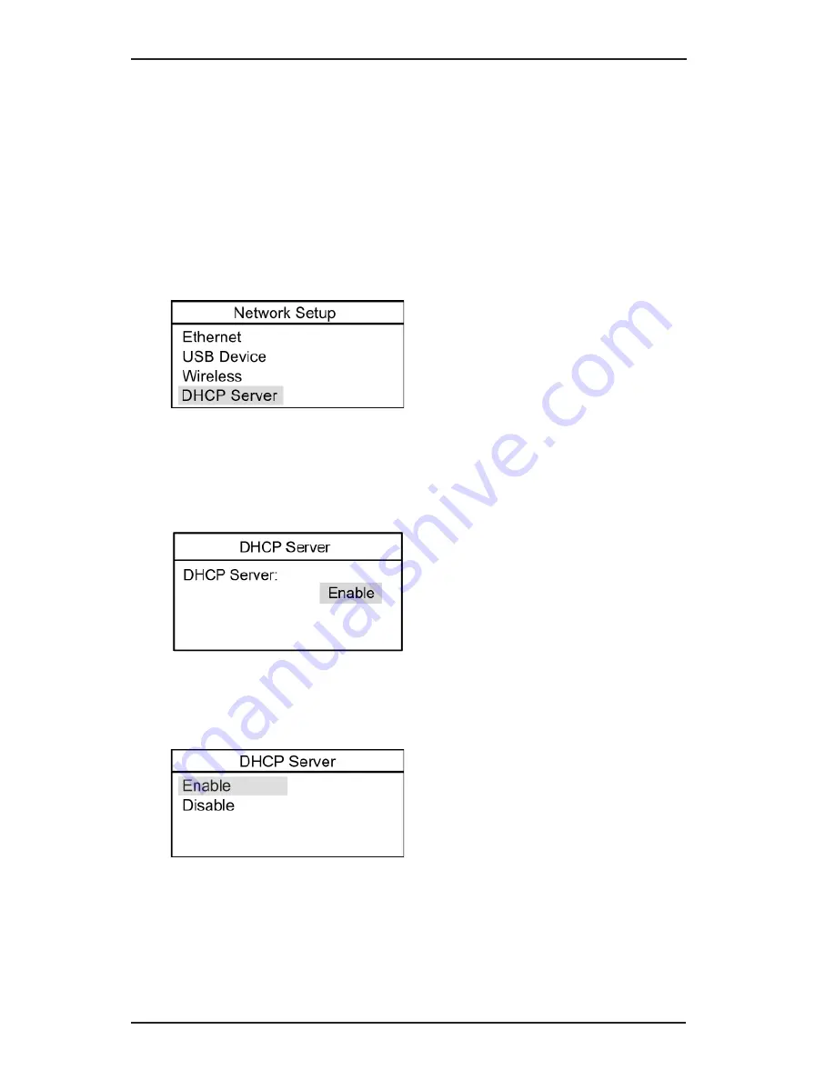
The DHCP server setting controls whether the MVCI will act as a 
DHCP server for Ethernet and USB operation. 

1. To 

change the DHCP server setting

, select 

DHCP Server

, press 

the 

ENTER

 button.

2. 

The display will show the current setting of the DHCP server. To 
enable/disable the DHCP server, 

highlight the current status,


press the 

ENTER

 button.


3. Select 

Enable or Disable

, press the 

ENTER

 button to save the 

change.

Summary of Contents for SPX MVCI

Page 1: ...Modular Vehicle Communication Interface User Guide...

Page 2: ...symbol appears on the MVCI It is important to follow the actions detailed in the User Guide Copyright No part of this manual may be reproduced stored in a retrieval system or transmitted in any form...

Page 3: ...da Diagnostic System HDS Setup 17 Connecting to the Vehicle 20 Wireless Network Setup 21 Step 1 Access Wireless Network Setup 21 Step 2 Select a Wireless Network Mode 22 Step 3 Select and Set Up Wirel...

Page 4: ...57 LED Test 58 LCD Test 58 Keypad Test 59 Scroll Test 60 Serial Number 60 Device Loopback Test 61 SDMEM Card Test 62 Auxiliary PC Applications 63 MVCI Discovery Wireless 63 MVCI Firmware Update 64 MVC...

Page 5: ...e around moving components or belts during testing Moving components and belts can catch loose cloth ing body parts or test equipment and cause serious damage or personal injury Refer to the service m...

Page 6: ...vehicle s Diagnostic Link Connector See Connecting to the Vehicle section of this User Guide for additional information The MVCI will require power from the vehicle to operate properly The MVCI is ty...

Page 7: ...Button or Off Button Enter Button USB Port Power Adapter Port Top Port Cover Secure Digital Wireless Card Wireless Card Locking Retainer Clip Status Lights Vehicle Communication Wireless Connection B...

Page 8: ...x 0 375 Important Damage will result and the warranty voided if a Battery Cover replacement screw exceeds 0 375 in length Protocol Expansion Board NiMH AA Batteries 2 Threaded Inserts 4 No 4 40 unc Fo...

Page 9: ...S is connected to the MVCI via a wireless connection Battery Icon Descriptions Title Bar Body Battery Charging Animation MVCI is charging the batteries Charged Battery Icon Charge cycle is completed N...

Page 10: ...vehicle Wireless Connection LED This LED lights solid blue when the wire less card is configured Battery Discharging LED When the MVCI is powered by its inter nal battery this LED first lights solid o...

Page 11: ...ista My Computer and click on the install CD under devices with removable storage Double click the file named Setup 2 a When installing on Windows XP a Software Installation window appears Click Conti...

Page 12: ...power supply into the MVCI to boot it up The following screen will appear 2 Using the USB cable supplied with the MVCI connect the MVCI to your PC If you are running Windows XP begin your set up with...

Page 13: ...13 4 The Found New Hardware Wizard screen continues and asks What do you want to do Select Install the software automatically Recommended Click Next...

Page 14: ...14 5 A Hardware Installation screen will appear click Continue Anyway 6 When the Installation is complete click Finish to close the wizard 7 Installation is now complete Restart the PC...

Page 15: ...15 Vista Setup 8 Windows Vista automatically installs the MVCI driver software Observe the status and completion of its installation from your PC desktop 9 Installation is now complete Restart the PC...

Page 16: ...ice setup in the User Guide Wireless Connection If the Wireless connection is chosen please refer to the Wireless Network Setup in the User Guide for setup instructions It is recommended to test USB c...

Page 17: ...c System HDS Setup The MVCI can be used with HDS software 1 Double click the HDS shortcut icon on the desktop to start the HDS 2 On the HDS Welcome Screen click the F12 tab NOTE Please install the lat...

Page 18: ...ect SPX MVCI in the drop down selection under Comms Interface 4 The following screen is displayed when SPX MVCI is selected Press the Enter button on your keyboard or click the green check mark locate...

Page 19: ...automatically restart and returns to the HDS Welcome screen NOTE If the following warning screen appears press the Enter button on your keyboard or click the green check mark and try again after HDS...

Page 20: ...he vehicle Diagnostic Link Connector 3 To turn off the MVCI disconnect from the vehicle Diagnostic Link Connector press the ESC button for 5 seconds The MVCI will also automatically power off in 60 se...

Page 21: ...rity 4 Set Up PC Communication to MVCI 5 Connect to MVCI Begin by automatically powering on the MVCI with the AC power supply Plug the power supply into the Power Adapter Port located on the bottom of...

Page 22: ...a Wireless Network Mode 2 a Select a Wireless Network Mode to set up Peer to Peer MVCI and PC communicate directly to each other in a private wireless network Access Point MVCI and PC communicate to...

Page 23: ...ng the available networks will appear Follow the screens for one of the two possible options that may appear If the Access Point is broadcasting an SSID go to Step 2 b 1 If the Access Point is not bro...

Page 24: ...d entering the SSID of the access point The SSID will then display the SSID of the network you have entered NOTE Record the SSID of the network selected for reference when you set up the PC to communi...

Page 25: ...screen select Security press ENTER If you do not want to use wireless security check to see that Disabled is displayed on the next screen Then skip this step and go to Step 4 Set Up PC Communication...

Page 26: ...Security Setup screen scroll down to Mode select the current Mode press ENTER 3 d Select the correct Mode press ENTER NOTE Open means that the MVCI may initiate communication with the Access Point Sh...

Page 27: ...e scroll up down to enter a number use left right to move to the next digit Press ENTER when finished then press the ESC button to return to the previous menu 3 g When you have finished selecting the...

Page 28: ...ect or connect with any other wireless device in the environment refer to the PC documentation to identify the specific solution to enable the wireless radio If you are running Windows XP begin your s...

Page 29: ...hnology IT Administrator for Access Point 4 g If the wireless security of the MVCI is an unsecured network a warning message is displayed Click Connect Anyway If the wireless security of the MVCI is a...

Page 30: ...the MVCI is completed IMPORTANT When you have completed your diagnostics make sure to disconnect Wireless Network Connection on the PC side and unplug the MVCI power supply Select the MVCI which is co...

Page 31: ...OR Double click Network and Sharing Center 4 l In the Network and Sharing Center window click on the Manage network connections label provided on the left side panel named Tasks 4 m Right click on you...

Page 32: ...int mode or a MVCI in Peer to Peer mode Click Connect NOTE Ask your Information Technology IT Administrator for Access Point 4 q If the wireless security of MVCI is an unsecured network a warning mess...

Page 33: ...d labeled Security key or passphrase Click Connect 4 r Select Save this network and click Close If you do not wish to save this network setting remove the checked selection and click Close NOTE If the...

Page 34: ...34 If the wireless security of MVCI is a security enabled network and you select Save this network the Network Location message is displayed Click the Network Location Work 4 s Click Close...

Page 35: ...ing Center is displayed when the connection is complete IMPORTANT When you have completed your diagnostics make sure to disconnect the Wireless Network Connection on the PC side and unplug the MVCI po...

Page 36: ...36 Step 5 Connect to MVCI 5 a On your PC desktop double click the MVCI Discovery Wireless icon a utility installed from the MVCI Drivers CD 5 b On the MVCI Discovery utility screen click Find SPX MVCI...

Page 37: ...network will display If you have your MVCI in Peer to Peer mode the MVCI selected in Step 4 f or 4 p will display 5 d Select a MVCI to use Click Connect to Selected MVCI Set up is complete and the MV...

Page 38: ...8 DLC Voltage 1 Power up the MVCI using the Vehicle Diagnostic Link After boot up press the ENTER button to enter the User Config screen 2 Select DLC Voltage 3 The vehicle battery voltage is displayed...

Page 39: ...tton to enter the User Config screen 2 Select MVCI Setup and press ENTER The following setup options are available Clock Language SDIO 1 SDIO 2 Keybeep Contrast Control Factory Defaults Clock 1 To cha...

Page 40: ...time highlight the Time and press ENTER Scroll up down to change the number and left right to move between the hours minutes and seconds fields Press ENTER to save the changes or ESC to cancel 3 Press...

Page 41: ...ll up down to move the cursor over the desired option Press ENTER to save the change or ESC to cancel SDIO 2 1 To enable disable the SDIO 2 card slot on the MVCI select SDIO 2 The current status of th...

Page 42: ...the Keybeep is displayed in the MVCI Setup menu Press ENTER to change status 2 From the Setup Screen move the cursor over the desired option press ENTER to save the change or ESC to cancel Contrast Co...

Page 43: ...l Factory Defaults To restore the MVCI to the factory default settings select Restore under Factory Defaults press ENTER IMPORTANT All Network configuration settings will be reset to the following val...

Page 44: ...ork Setup Power up the MVCI After boot up press the ENTER button to enter User Config screens Select Network Setup and press ENTER The following setups are available Ethernet USB Device Wireless DHCP...

Page 45: ...ot included 1 To change the Ethernet network settings select Ethernet press the ENTER button 2 To change the IP Address highlight the IP Address and press the ENTER button Scroll up down to change the...

Page 46: ...t right to move between the components of the subnet mask Press the ENTER button to accept the changes then press the ESC button to return to the previous menu To return to the previous menu without a...

Page 47: ...work settings select USB Device press the ENTER button 2 To change the IP Address highlight the IP address and press the ENTER button Scroll up down to change the number and left right to move between...

Page 48: ...urn to the previous menu To return to the previous menu without accepting the changes press the ESC button 4 To save your changes scroll down to the Network Service option and press the ENTER button W...

Page 49: ...odes For Peer to Peer connection the Service should be set to Static For Access Point connection the Service should be set to DHCP Client This change should occur automatically when the Network Mode i...

Page 50: ...the changes press the ESC button 6 To change the Subnet mask highlight the Subnet mask and press the ENTER button Scroll up down to change the number and left right to move between the components of t...

Page 51: ...een will show the Connections screen 9 From the LAN Setup see illustration above select View under Config press the ENTER button The Connections screen displayed next is for information confirmation o...

Page 52: ...g controls whether the MVCI will act as a DHCP server for Ethernet and USB operation 1 To change the DHCP server setting select DHCP Server press the ENTER button 2 The display will show the current s...

Page 53: ...ot up press the ENTER button to enter the User Config screens Select System Status and press ENTER The following setup options are available SDIO 1 SDIO 2 Battery Charger Host Status SDIO 1 To view th...

Page 54: ...The information for SDIO slot 1 is typically for the MVCI memory card SDIO 2 To view the status of SDIO slot 2 select View status Status screens appear scroll down to see all status items The screens...

Page 55: ...emperature of the MVCI is at or above 60 degrees centigrade Battery charging will resume once the MVCI power is cycled turned off and on and temperature is below 60 degrees centigrade Host Status This...

Page 56: ...After boot up press the ENTER button to enter the User Config screens Select Software Version and press ENTER Scroll down to see the remaining software versions displayed NOTE Software screens show e...

Page 57: ...onfig screens Select Hardware Test and press ENTER The following setup options are available Buzzer Test LED Test LCD Test Keypad Test Scroll Test Serial Number Device Loopback Test SDMEM Card Test Bu...

Page 58: ...s LCD Test Select LCD Test press the ENTER button to start a series of LCD tests 1 Press ENTER all pixels are set to the on position Press ESC to exit from the LCD test 2 After 5 seconds the following...

Page 59: ...xit from the test Keypad Test Select Keypad Test press the ENTER button to start the Keypad test To test the keypad move around the scroll pad until all of the numbers are highlighted The 1 digit will...

Page 60: ...the scroll function move your finger around the scroll pad clockwise to scroll down Move your finger around the scroll pad counter clockwise to scroll up Press the ESC button to exit the scroll test S...

Page 61: ...the MVCI is being powered through the vehicle cable Run this test only when the MVCI is powered by the AC power adapter The following screen appears When the test is complete a pass or fail screen wi...

Page 62: ...either of the SDIO slots Select the SDMEM Card Test press the ENTER button to start the SDMEM Card Test The following screen appears When the test is finished the condition of the card will display Th...

Page 63: ...Wireless This application is used to determine which MVCI to connect to when using a wireless connection To launch the application do one of the following Click the MVCI Discovery desktop icon Click...

Page 64: ...independent of the Honda Diagnostic System HDS This application should not be used unless specifically directed to by Technical Service To launch the application do one of the following Double click...

Page 65: ...mmunicate to the MVCI This program also provides a mechanism to generate a MVCI debugging file This application should not be used unless specifically directed to by Technical Service Click All Progra...

Page 66: ...e connected to a vehicle or an external power source The MVCI will power off after sixty seconds without external power Why does my MVCI keep rebooting when the external power is disconnected The MVCI...

Page 67: ...l changes must be saved before the MVCI automatically returns to the Host Status display Why does the battery icon on the Host Status screen have an X in it The batteries are not installed or are inst...

Page 68: ...facing you slide the retainer clip to the right 3 Remove the retainer clip and place it in a safe area 4 Push the SD wireless card inward and release The SD wireless card will release and eject parti...

Page 69: ...CI or plugging in SDIO or SD memory cards Use only parts supplied with or recommended for use with your MVCI Pay attention to the condition and position of connectors to make connections properly Do n...

Page 70: ...tware communicate by USB cable No Turn ignition switch to the ON position No Disconnect the MVCI from the vehicle connector and then Plug in the external power supply No Is the power to the MVCI ON Ye...

Page 71: ...ms Interface set to SPX MVCI Yes No On the HDS welcome screen click the F12 button Is SPX MVCI present in the drop down selection of Comms Interface No Can the HDS software communicate if the MVCI is...

Page 72: ...le and then press ENTER Scroll up to change to Enable Press ENTER to save the change Please investigate the wireless setup of the PC and the setup of the Access Point Perform the MVCI wireless setup d...

Page 73: ...NiMH 2000mAh SPX P N H550175 AC Adapter Input 100 240V AC 50 60Hz Output 15V DC 1 2A SPX P N H547571 Vehicle I O 26 pin Connector The MVCI is capable of taking voltage measurements on the vehicle diag...

Page 74: ...74...

Page 75: ...Modelo SPX MVCI 0984 09 4188 01 07898939454017...

Reviews: