PUBLICATION FOR DEALER USE ONLY. NOT FOR RESALE OR DISTRIBUTION.
© American Honda
Motor Co., Inc.—All rights reserved
white
green
Page 1: ...ould perform a given task Important Safety Precautions Make sure you have a clear understanding of all basic shop safety practices and that you are wearing appropriate clothing and using safety equipm...
Page 2: ...del GX360Kl I Type 4 stroke O H C P cylinder Displacement Bore x Stroke Maximum horsepower Maximum torque 359 cc 21 9 cu in 58 x 68 mm 2 3 x 2 7 in I 12 2 HP at 3 600 rpm 24 N m 240 kg cm 17 3 ft lb a...
Page 3: ...c a n H o n d a M o t o r C o I n c A l l r i g h t s r e s e r v e d GENERATOR Item Model EV6010 Tvw Maximum output Rated output Rated voltage Rated current Rated frequency Phase Voltage regulating...
Page 4: ...el EV6010 Voltage variation rate Momentary 15 Max 1 Average 7 Average time 3 set Frequency variation rate Momentary 15 I I Max Averaae 7 I 1 Average time Voltage stability Frequency stability Rated po...
Page 5: ...r C o I n c A l l r i g h t s r e s e r v e d PERFORMANCECURVES The following charts show generator performance under standard condition Generator performance will decrease at high temperatures and o...
Page 6: ...I B U T I O N A m e r i c a n H o n d a M o t o r C o I n c A l l r i g h t s r e s e r v e d DIMENSIONAL DRAWINGS UNDER GENERATOR EXHAUST SYSTEM Unit mm in 765 30 11 4 5 75 3 SIDE MOUNTING EXHAUST SY...
Page 7: ...DIMENSIONS AND CLEARANCES The compartment walls not the mounting tray should be lined with fiberglass or other nonflammable acoustic insulation material The acoustic insulation reduces the space withi...
Page 8: ...Indicates that equipment or property damage could result if instructions are not followed l Stop the engine and remove the spark plug caps and ignition key before servicing the generator l If the engi...
Page 9: ...c a n H o n d a M o t o r C o I n c A l l r i g h t s r e s e r v e d SERIAL NUMBER LOCATIONS The frame serial number is stamped on the soundproof cover and the engine serial number is on the crankcas...
Page 10: ...agonally unless a particular sequence is specified 5 Clean parts in cleaning solvent upon disassembly Lubricate any sliding surface before reassembly 6 After reassembly check all parts for proper inst...
Page 11: ...O 14 mm 0 004 0 006 in cold EX 0 18 0 22 mm 0 007 0 009 in Stem O D IN 5 48 mm 0 216 in 5 32 mm 0 209 in EX 5 45 mm 0 215 in 5 29 mm 0 208 in Guide I D INlEX 5 50 mm 0 217 in 5 55 mm 0 219 in Seat wid...
Page 12: ...0 6 kg cm 5 7 8 5 psi Thermoswitch Temperature for continuity 105OC 221 OF Choke solenoid Temperature for continuity 16 5 23 5OC 62 74OF thermoswitch Engine Temperature for continuity 120 13O C 248 2...
Page 13: ...0 75 Ml6 x 1 5 M30 x 1 0 Ml0 x 1 25 M8 x 1 25 Ml6 x 1 5 Ml6 x 1 5 M5 x 0 8 l 8 NPT l 8 NPT 7 l 6 24UNS Ml0 M8 118 8SPT 5 mm screw bolt nut 6 mm screw flange bolt SH TYPE 6 mm bolt nut 6 mm flange bol...
Page 14: ...mm I D 19 Valve guide reamer 5 5 mm 20 Remover bolt 21 Attachment 35 mm I D __ s Tool number 07401 0010000 07757 0010000 07781 PO301OA 07781 P03020A 07781 P03030A 07780 PO1030A 07780 PO1040A 07780 PO1...
Page 15: ...n diagram in figure below is an overview of the way each part depends upon the others for power and or information COMPONENT FUNCTION l EV6010 generators with 3 fuse control box frame numbers 1000001...
Page 16: ...h the control box and the AVR begins the generator field 2 Output from the exciter winding is rectified in the AVR and sent to the field 3 Sensor winding signal is read by the AVR and used to control...
Page 17: ...motor CONTROL Box step 411 l Faulty Fl fuse holder 2 fuse models or Fl or F2 fuse holder Sfuse models or loose wire ICONTROL Box step 511 l Faulty starter switch CONTROL BOX step 611 l Faulty control...
Page 18: ...rrect valve clearance IINSPECTION Incorrect valve timing INSPECTIONI Sticking worn or burnt valves INSPECTION Worn or damaged piston rings piston or cylinder INsPECT ON l Carburetor INSPECTION Clogged...
Page 19: ...r AVR stator or rotor GENERATOR TROUBLESHOOTING l Faulty control unit ICON ROL BOX I 2 Does the red temperatur on when the engine stops No l Low engine oil level INSPECTION glow engine oil pressure TR...
Page 20: ...d air leak IINSPECTION l Cylinder head gasket leak INSPECTIONI 1 Remove spark plugs 2 Attach the spark plugs to the caps and ground the side elec trode to the engine NOTE l The other spark plug cap mu...
Page 21: ...rature CAUTION l To prevent engine damage from low oil pressure carefully monitor the oil pressure while the engine is war c I Specified oil pressure 2 0 kg cm 28 4 psi minimum 5 If the oil pressure i...
Page 22: ...Use an ohmmeter to check the fuses and fuse holders 4 Use the correct length diameter and capacity fuse Troubleshooting Generator Symptoms a Push start button starter motor does not operate See page...
Page 23: ...R D E A L E R U S E O N L Y N O T F O R R E S A L E O R D I S T R I B U T I O N A m e r i c a n H o n d a M o t o r C o I n c A l l r i g h t s r e s e r v e d EV6010 6 444 a Push start button starte...
Page 24: ...P U B L I C A T I O N F O R D E A L E R U S E O N L Y N O T F O R R E S A L E O R D I S T R I B U T I O N A m e r i c a n H o n d a M o t o r C o I n c A l l r i g h t s r e s e r v e d EV6010 6 445...
Page 25: ...P U B L I C A T I O N F O R D E A L E R U S E O N L Y N O T F O R R E S A L E O R D I S T R I B U T I O N A m e r i c a n H o n d a M o t o r C o I n c A l l r i g h t s r e s e r v e d EV6010 6 446...
Page 26: ...e carburetor bowl for contaminates Clean as necessary Is the carburetor getting fuel Check for clogged fuel line or filter Check fuel pump operation c Choke Does the choke system operate properly d Ig...
Page 27: ...P U B L I C A T I O N F O R D E A L E R U S E O N L Y N O T F O R R E S A L E O R D I S T R I B U T I O N A m e r i c a n H o n d a M o t o r C o I n c A l l r i g h t s r e s e r v e d EV6010 6 448...
Page 28: ...two possible causes of the problem 1 The remote is not wired correctly The brown and white Honda colors wires are reversed See page 13 1 of the base shop manual for correct wiring 2 The wire in the re...
Page 29: ...S A L E O R D I S T R I B U T I O N A m e r i c a n H o n d a M o t o r C o I n c A l l r i g h t s r e s e r v e d EV6010 6 450 d Push the start button engine starts but green light does not come on...
Page 30: ...A T I O N F O R D E A L E R U S E O N L Y N O T F O R R E S A L E O R D I S T R I B U T I O N A m e r i c a n H o n d a M o t o r C o I n c A l l r i g h t s r e s e r v e d EV6010 6 451 Go to page 6...
Page 31: ...P U B L I C A T I O N F O R D E A L E R U S E O N L Y N O T F O R R E S A L E O R D I S T R I B U T I O N A m e r i c a n H o n d a M o t o r C o I n c A l l r i g h t s r e s e r v e d EV6010 6 452...
Page 32: ...A T I O N F O R D E A L E R U S E O N L Y N O T F O R R E S A L E O R D I S T R I B U T I O N A m e r i c a n H o n d a M o t o r C o I n c A l l r i g h t s r e s e r v e d EV6010 6 453 Go to page 6...
Page 33: ...irs see page 5 2 COMPLAINT Abnormal output none low or high at the receptacle Normal 120 VAC 10 The circuit breaker must be in the ON position Push and hold the start button until the engine starts an...
Page 34: ...umper lead to the ignition primary grounding wire to the female connector so the engine may be stopped when necessary b Unplug the fuel pump power lead red Attach a jumper wire from the red wire male...
Page 35: ...B L I C A T I O N F O R D E A L E R U S E O N L Y N O T F O R R E S A L E O R D I S T R I B U T I O N A m e r i c a n H o n d a M o t o r C o I n c A l l r i g h t s r e s e r v e d EV6010 6 456 EV60...
Page 36: ...E A L E R U S E O N L Y N O T F O R R E S A L E O R D I S T R I B U T I O N A m e r i c a n H o n d a M o t o r C o I n c A l l r i g h t s r e s e r v e d EV6010 6 459 GENERATOR TEST POINTS EV6010 Se...
Page 37: ...D E A L E R U S E O N L Y N O T F O R R E S A L E O R D I S T R I B U T I O N A m e r i c a n H o n d a M o t o r C o I n c A l l r i g h t s r e s e r v e d EV6010 6 462 WIRING DIAGRAM EV6010 Serial...
Page 38: ...Stop the engine before performing any maintenance If the engine must be running make sure the area is well ventilated Engine exhaust contains poisonous carbon monoxide gas _ CAUTION l Only use new gen...
Page 39: ...ug and tighten it securely If changing the oil filter coat the seal with clean engine oil and screw on the filter until the seal contacts the filter mounting base Then use a oil filter wrench to tight...
Page 40: ...E 5 Clean the air filter elements if they are to be reused Paper element Tap the filter element several times on a hard surface to remove dirt or blow compressed air not exceeding 207 kPa 30 psi throu...
Page 41: ...Remove carbon or other deposits with a stiff wire brush 6 Measure the plug gap with a wire type feeler gauge Spark plug gap 0 7 0 8 mm 0 028 0 031 in If necessary adjust the gap by bending the side e...
Page 42: ...e s e r v e d SPARK ARRESTER l If the generator has been running the exhaust system will be very hot and can cause severe burns Allow it to cool before proceeding 1 Remove the bolt from the bottom of...
Page 43: ...linder block 5 Check the intake and exhaust valve clearances for the cylinder that is at top dead center of its compression stroke by inserting a feeler gauge between the valve stem and the adjusting...
Page 44: ...P U B L I C A T I O N F O R D E A L E R U S E O N L Y N O T F O R R E S A L E O R D I S T R I B U T I O N A m e r i c a n H o n d a M o t o r C o I n c A l l r i g h t s r e s e r v e d...
Page 45: ...P U B L I C A T I O N F O R D E A L E R U S E O N L Y N O T F O R R E S A L E O R D I S T R I B U T I O N A m e r i c a n H o n d a M o t o r C o I n c A l l r i g h t s r e s e r v e d...
Page 46: ...ide the fuel tank 2 Disconnect the fuel line from the fuel line filter being careful not to spill the fuel 3 Turn the fuel line filter counterclockwise and remove it from the fuel pump 4 Apply thread...
Page 47: ...Loosen the radiator cap Relieve the pressure inside the radiator and retighten the cap 2 Remove the drain plug then remove the radiator cap and drain the coolant from the system Remove and empty the...
Page 48: ...on Use high quality ethylene glycol antifreeze that is specificalh formulated for use in aluminum engines Mix the antifreeze with low mineral drinking water or distilled water A 50 50 mixture of ethyl...
Page 49: ...d connector 3 Disconnect ihe two leads from the radiator thermoswitch 4 Remove the two 6 x 30 mm flange bolts and remove the radiator 1REASSEMBLY Install the hose clamp on the radiator pipe between th...
Page 50: ...ch end in oil NOTE Il Don t allow the thermometer or the thermoswitch to touch the bottom of the container this will cause a false reading I 2 Heat the oil and measure the oil temperature when continu...
Page 51: ...n d a M o t o r C o I n c A l l r i g h t s r e s e r v e d AIR CLEANER a DISASSEMBLY REASSEMBLY CRANKCASE BREATHER HOSE NNECTING TUBE BAND fi CONNECTING TUBE RESERVE TANK AP EANER STAY RESERVE TANK C...
Page 52: ...efore in stalling TORQUE 13 2 N m 1 35 kg m 9 8 ft lb I FUEL PUMP JOINT NUT i REASSEMBLY Apply thread locking agent to the threads before installing TORQUE 17 5 N m 1 75 kg m 12 7 ft lb I I FUEL PIPE...
Page 53: ...U B L I C A T I O N F O R D E A L E R U S E O N L Y N O T F O R R E S A L E O R D I S T R I B U T I O N A m e r i c a n H o n d a M o t o r C o I n c A l l r i g h t s r e s e r v e d GENERAL INFO 19...
Page 54: ...T Place the carburetor in an upright position and measure the dis tance between the float top and carburetor body when the float just contacts the seat without compressing the valve spring I I Standar...
Page 55: ...e pump 5 Connect a vacuum gauge to the fuel filter nipple 6 Connect the battery again and measure the vacuum Nor mal reading should be 12 2 4 cm Hg 5 2 in Hg If the gauge reading is less replace the p...
Page 56: ...P U B L I C A T I O N F O R D E A L E R U S E O N L Y N O T F O R R E S A L E O R D I S T R I B U T I O N A m e r i c a n H o n d a M o t o r C o I n c A l l r i g h t s r e s e r v e d...
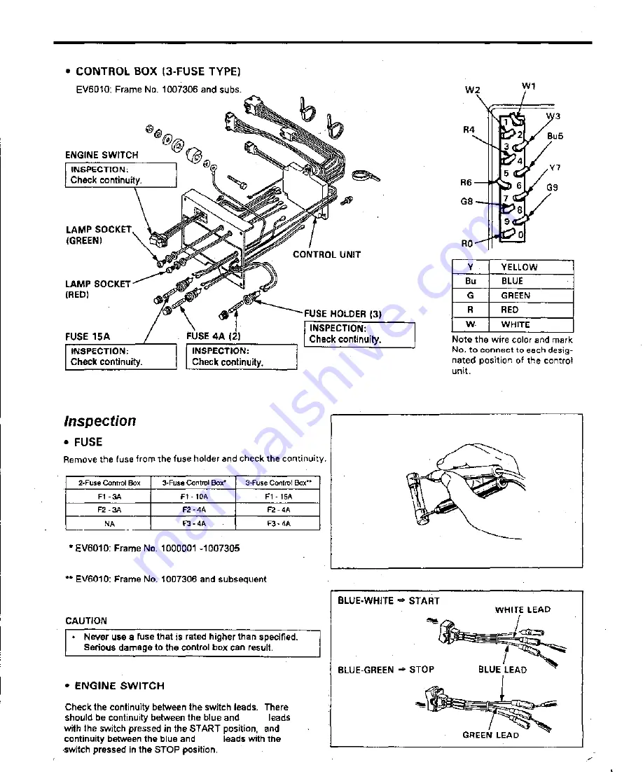
Page 57: ...om components to control differrent operations of the generator b DISASSEMBLY REASSEBMBLY CAUTION l The control circuits will not function if the control box is not grounded properly The control box m...
Page 58: ...P SOCKET _ GREEN LAMP SOCKET CAlIf CONTROL UNIT FUSE HOLDER 2 FUSE 3A 21 CONTROL BOX 3 FUSE TYPE EV6010 Frame No 1000001 1007305 TERMINAL COLLAR A ENGINE SWITCH LAMP SOCKET LAMP SOCKE FUSE HOLDER 3 FU...
Page 59: ...ve the fuse from the fuse holder and check the continuity Z Fuse Control Box 3 Fuse Control Box 1 3 Fuse Control Box Fl 3A Fl 1OA Fl 15A F2 3A F2 4A F2 4A NA F3 4A F3 4A l EV6010 Frame No 1000001 1007...
Page 60: ...y terminal Bus strip Wl F2 3A Red lead side terminal of fuse holder Bus strip R6 EV6010 Generators With 3 Fuse Control Box Frame Serial Numbers 1000001 1007305 3 Fuse Control Box Fl 10 A Battery termi...
Page 61: ...net DISASSEMBLY Jse the special tool and a ommercially available slide lammer ro prevent the rotor from ailingwhenremoved placea wooden blockand rag under reath the rotor or supportit withyour hand S...
Page 62: ...et the stator with the solid core laminates resting on the work surface FAN STATOR TROUBLESHOOTING ROTOR TR UBLES O TIN 14 mm SELF TAPPING EW 3 STATOR COVER BREAKE R LEAD 2 5 x 10 mm SELF TAPPING SCRE...
Page 63: ...r e s e r v e d EV60 10 A TYPES EV6010 LA RA FA EA TYPES 6 PIN CONNECTOR To A V R Blue Yellow AC OUTPUT Blue 0 Gray Yellow Red 2 PIN CONNECTOR NG FAN k BRUSH HOLDER BRUSHES tireen wrounul I a 5P CONN...
Page 64: ...the R x 1 scale of an ordinary analog multimeter Some meters show current flow from negative 1 to positive 1 and others show flow from positive to negative 1 The polarity of the meter does not matter...
Page 65: ...r i c a n H o n d a M o t o r C o I n c A l l r i g h t s r e s e r v e d ENGINE FRAME EYGINE MOUNT STOPPER 21 ENGINE I 8 x 16 21 SHROUD STAND 8 mm PLAlN WA SHROUD STAND 8 mm FLANGE NUT ENGINE MOUNT S...
Page 66: ...S E O N L Y N O T F O R R E S A L E O R D I S T R I B U T I O N A m e r i c a n H o n d a M o t o r C o I n c A l l r i g h t s r e s e r v e d WIRE HARNESS CABLE CLAMP BOLT 8x16 6 mm FLANGE BOLT 13...
Page 67: ...mm OVAL INTAKE MANIFOLD HEAD SCREW I ELBOW GASKET OUTER EXHAUST COVER I 6n nm FAIRING BOLT 3 6 mm FLANGE BOLT 10 6 x 25 2 AINTAKE MANIFOLD ELBOW INTAKE MANIFOLD GASKET 8 mm FLANGE NUT 2 2 ka m 1 6 x 5...
Page 68: ...a DISASSEMBLY REASSEfi 6 28 2 I REASSEMBLY l Use genuine HONDA timing belt l Check that the belt is not worn or cracked Do not bend or twist the belt REPLACEMENT ADJUSTMENT INSPECTION 7 O RING 6 x 10...
Page 69: ...ified torque TORQUE 113 N m 11 5 kg m 83 2 ft lb l CAMSHAFT PULLEY DISASSEMBLY Remove the camshaft pulley using the remover bolt special tool l TIMING PULLEY DISASSEMBLY Install the woodruff key in th...
Page 70: ...tion 5 Align the T mark on the cam pulley with the A mark on the cylinder block and align the A mark on the timing pulley with A mark on the cylinder block Install a new timing belt over the pulleys A...
Page 71: ...caps are not removed l SPARK PLUG CAP Measure the resistance of the spark plug cap by touching one test lead at the wire end of the cap and the other at the spark plug end I Resistance 7 5 12 5 kfl Re...
Page 72: ...t s r e s e r v e d STARTER MOTOR a DISASSEMBLY REASSEMBLY 8 x 20 R ENGINE MO ING BRACKET 8x 28 2 10 x 12 mm DOWEL STARTER MOTOR ASSEMBLY PIN 2 L ENGINE MOUNTING BRACKET BRUSH HOLDER Retract the brush...
Page 73: ...3 mm 0 37 in l INSULATION BETWEEN BRUSHES Check for continuity between brushes There should be continuity between both positive brushes There should be continuity between both negative brushes There s...
Page 74: ...ontinuity between the commutator and armature coil core If continuity exists replace the armature SHORT CIRCUIT TEST SHAFT TO COMMUTATOR Check for continuity between the commutator and armature shaft...
Page 75: ...ENGINE THERMOSWITCH IAIR BLEEDING 1 INSPECTION RMOSTAT tall with the pin fac THERMOSTAT COVER RADIATOR CAP INSPECTION I v WATER I GOVERNOR SLIDER CHOKE SOLENOID THERMOSWITCH BALANCER WEIGHT 3 IINSPEC...
Page 76: ...thermoswitch in water that s temperature is below 15OC 59OF 2 Measure the water temperature when continuity occures NOTE l Don t let the thermometer or the choke solenoid ther moswitch touch the bott...
Page 77: ...NG COMPRESSOR 07757 0010000 1 VALVE STEM SEAL 4 VALVE SPRING 4 t I fwpq VALVE SPRING RETAINER 4 the valve stem slips through the hole at the l6x2Bx6mm OILSEAL EXHAUST VALVE 2 INTAKE VALVE IN 28 mm 1 1...
Page 78: ...ings if they are shorter than the service limit l ROCKER ARM SHAFT O D I STANDARD I SERVKE LIMIT I 12 957 mm 0 5101 in 12 940 mm 0 5094 in l ROCKER ARM I D STANDARD SERVICE LIMIT 13 015 mm 0 5124 in 1...
Page 79: ...mm 0 004 0 006 in EX 0 18 0 22 mm 0 007 0 009 in If the stem to guide clearance exceeds the service limit deter mine if the new guide with standard dimensions would bring the clearance within toleran...
Page 80: ...valent I To avoid burns use heavy gloves when handling the heated cylinder head CAUTION l Do notuse a torch to heat the cylinder head warpage of the cylinder head may result l Do not get the head hott...
Page 81: ...the valve guide bore it should be straight round and centered in the valve guide insert the valve and check oper ation If the valve does not operate smoothly the guide may have been bent during instal...
Page 82: ...OLID PILOT BARS 5 50 mm 07781 P03010A 5 52 mm 07781 P03020A 5 55 mm 07781 P03030A T WRENCH 505 07782 P01010A T WRENCH ADAPTER 503 l 07782 P01020A ACCESSORY PACKAGE 246 07782 P01030A VALVE SEAT CUTTERS...
Page 83: ...compound or erasable felt tipped mar ker ink to the valve faces Insert the valves and snap them closed against their seats several times Be sure the valve does not rotate on the seat The seating surfa...
Page 84: ...WITCH OIL FILTER WRENCH l Apply thread locking agent I 07HAA PJ70100 to the threads of the plug LING WASHER OIL GALLERY PLUG RADIAL BALL BEARI PISTON 6x 1414 CONNECTING ROD THRUST BEARING 1 I groove s...
Page 85: ...IN CLIP PT AL Il Install the piston so that the valve reliefs are on the valve I CONNECTING ROD DISASSEMBLY Mark the rods so they can be in inal positions Apply oil when assembling the THRUST BEARING...
Page 86: ...essary replace them l PISTON SKIRT 0 D Measure and record the piston 0 D at a point 10 mm 0 4 in from the bottom of the skirt and 90 to the piston pin bdre STANDARD SERVICE LIMIT 57 97 mm 2 282 in 57...
Page 87: ...MIT TOP SECOND 0 03 mm 0 001 in 1 I 7 mm 0 007 in l CYLINDER I D I I Measure and record the cylinder I D at three levels in both X axis perpendicular to crankshaft and Y axis paralleJ to crank shaft T...
Page 88: ...SHAFT MAIN JOURNAL 0 D STANDARD SERVICE LIMIT 33 009 mm 1 2996 in 32 96 mm 1 298 in l CRANKSHAFT AXIAL CLEARANCE STANDARD SERVICE LIMIT 0 2 0 4 mm 0 008 0 016 in 0 6 mm 0 024 in l CRANKPJN 0 D STANDA...
Page 89: ...N JOURNAL BEARlFiG SELECTION Record the crankshaft main journal 0 D code numbers or measure the main journal 0 D Record the crankcase I D code numbers or measure the I D of the crankcase main journal...
Page 90: ...I D code letters or measure the I D with the bearing cap installed without the bearing inserts Cross reference the crankpin and rod codes to determine the replacement bearing color I REASSEMBLY Be car...
Page 91: ...R D I S T R I B U T I O N A m e r i c a n H o n d a M o t o r C o I n c A l l r i g h t s r e s e r v e d OILPUMP a DISASSEMBLY REASSEMBLY OIL PUMP GEAR O RING PACKING INNER ROTOR INSPECTION REASSEMB...
Page 92: ...e clearance between the inner and outer rotors STANDARD SERVICE LIMIT 0 17 mm 0 007 in 0 35 mm 0 014 in I l OUTER ROTOR CLEARANCE Install the outer rotor into the pump body and measure the clear ance...
Page 93: ...ctors and connect the control box to the re mote control unit MINIMUM WIRE GAUGE 1 25 mm2 16 gauge for distances up to 10 meters 33 feet 3 Install the remote control unit using four 3 mm 0 12 in screw...
Page 94: ...ION l REMOTE CONTROL Check for continuity between the leads There should be continuity between the white and brown leads with the engine switch pressed to START and continuity be tween the green and b...
Page 95: ...R R E S A L E O R D I S T R I B U T I O N A m e r i c a n H o n d a M o t o r C o I n c A l l r i g h t s r e s e r v e d MUFFLER a DISASSEMBLY REASSEMBLY A TYPES MUFFLER STAY 2 8 mmFLANGE NUT 4 MUFFL...
Page 96: ...C o I n c A l l r i g h t s r e s e r v e d l LA RA Types CLAMP REASSEMBLY Position the retaining plate of the clamp at a right angle with the slit as shown CLAMP 0 04 0 12 in SLIT 8 mm FLANGE NUT 2 8...
Page 97: ...e d l FA BA Types 6 x 12 21 10 N m 1 0 kg m 7 2 ft lb RUBBER 10 mm FLANGE NUT MOUNT 34 N m 3 5 kg m 25 3 ft lb 3 SPARK ARRESTER BRACKET I i urih I SPARK ARRESTER I CLAMP y y MOUNTING BRACKET 3 8tijyq...