


ENGLISH | 31
The rated (nominal) values can be found on the type plate.
Nominal input data relate to:
• an ambient temperature of -20 °C to 40 °C
• maximum temperature of the medium 40 °C
• continuous operation S1 and
• rated supply voltage
The connecting cables are designed for rated operation
where they are:
• separately routed,
• permanently submerged and/or attached to surfaces
and/or passing through air, and
• at a maximum ambient temperature of 40 °C
If the routing and/or ambient temperature of the connect-
ing cables differs from this, the standards and regulations
applicable at the installation site must be observed.
If the type of operation and/or rated power supply is dif-
ferent, the tolerances specified in EN 60034 must be ob-
served and the installation adjusted in accordance with
the standards and regulations applicable at the installation
site.
Note:
Conditions at the installation site must conform to all de-
tails on the rating plate.
In the case of uncertainty, the manufacturer must be con-
sulted before commissioning.
3.3.2. Motor
The three-phase asynchronous motor consists of a stator
and the motor shaft with the rotor package. The line for
the current supply is designed for the maximum mechan-
ical power according to the characteristic or type label of
the pump. The cable entries as well as the line are sealed
with pressurized water against the conveying medium.
The bearings are supported by robust, maintenance-free
and permanent lubricated bearings.
All motors are also available in explosion-proof design
according to ATEX Ex II 2 G EExd.
General Motor data
Service factor
1.15
Operating mode
S1
Insulation class
H (180°C)
Degree of protection
IP68
Cable length
10 m
Cable protection hose 5 m
Rotor shaft seal
Silicon-carbide / Silicon-carbide
Mechanical shaft seal Silicon-carbide / FPM
Bearing
one grooved ball bearing (above)
one double-row type angular ball bearing
(below)
two grooved ball bearing (below at CTP70…)
3.3.3. Control devices
The pump is equipped with various safety and control
devices. The following table shows an overview of the
available options. Options may vary depending on the size
of the pressure port.
Motor
Version
All
Temperature monitoring in the winding
...EX
Temperature monitoring in the winding, Explosion proof
Temperature Sensors
The explosion proof models have a set of temperature
sensor built in the stator windings. On request, tempera-
ture sensors are also available for the normal version.
For standard
1-phase
motors, the temperature sensors (if
installed) are internally connected in the motor so that no
special connection is necessary. After cooling, the motor
will automatically switch back on.
For all 1-phase motors in standard version, the connec-
tions of the temperature sensors (if installed) are routed
to the outside via the motor connection cable and are to
be connected in the control cabinet via the wire ends T1
and T3 in such a way that an automatic restart occurs after
the engine has cooled down. The explosion-proof versions
(1 phase and 3 phases) also have a set of temperature
sensors which must be connected via the wire ends T1
and T2 of the connection cable in such a way that a manu-
al reset is required after tripping. There are self-contained
Ex-probes instead of the standard probes, i. In the case
of a series circuit for protection, these can be reset by
disconnecting the pump from the mains (plug or main
switch) and waiting for the cooling.
The temperature sensor set must be connected in the
switchgear, which switches it off when it is overheated.
Switch-off temperature of the sensors:
Motor
Stator winding Normal
T1+T3 Regulator
Stator winding Ex
T1+T2 Limiter
AM122…C-2/4pol 140°C
140°C
AM136…D-2/4pol 140°C
140°C
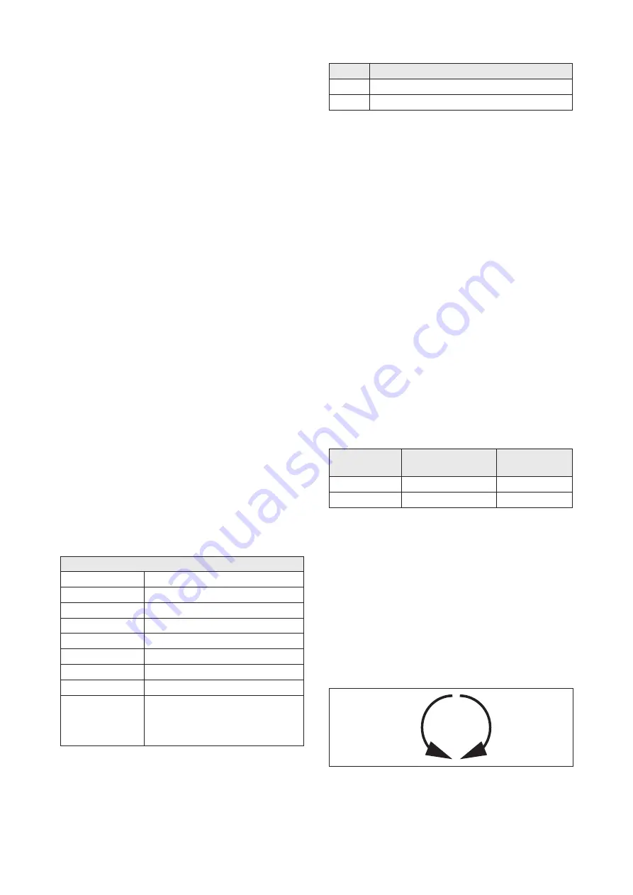
Check of Direction of Rotation
All pumps have the correct direction of rotation when
connected to a right rotating field (U, V, W -> L1, L2, L3).
HOMA switches check the mains for the right rotation
field. If there is no right-hand rotation, the red LED is
lit. Two phases are to be exchanged at the input of the
switchgear. In the case of smaller pumps, monitoring can
be carried out by observing the start-back. To do this, place
the pump vertically on the ground and turn it on briefly.
When viewed from above, the pump is slightly count-
er-clockwise when the direction of rotation is correct. The
correct direction of rotation of the pump is given when the
pump moves counterclockwise, as the motor is clockwise
as viewed from the top.
ST
AR
T
REACTION
ROTOR
REACTION
ATTENTION
The
direction of rotation
is correct if the
impeller/propeller rotates
in a
clockwise
manner
when viewing down from
top of the placed unit
ATTENTION
The
start reaction
is
anti clockwise
For large pumps, the direction of rotation can also be seen
by looking into the pump chamber through the pressure
port. The impeller can be seen here and can be switched
on after a short while, when the impeller runs out, check
the direction of rotation
Summary of Contents for CTP 50
Page 45: ...ENGLISH 45 Notizen Notes...
Page 71: ...71...