


11
3.3. Operating Conditions
Maximum liquid temperature:
35°C, short term up to
60°C.
Density of pumped liquid:
max. 1100 kg/m
3
Ph-value of pumped liquid:
6 up to 8.
Level of pumped liquid:
The lowest level must always be
above the top of the pump housing (volute).
Operation:
The motors are designed for continuous op-
eration (S1) with fully submerged motor, maximum 15
starts per hour. Our standard warranty and maintenance
regulations refer to intermittent operation. For reduced
warranty periods and service intervals due to continuous
operating conditions please contact our service
department.
3.4. Explosive Environments
For operation of the pumps in explosive environments
only models with explosion-proof motors must be used
(see HOMA product range).
4. Warranty
Our warranty only covers pumps which are installed and
operated in accordance with these installation and opera-
tion instructions and accepted codes of good practice and
being used for the applications mentioned in these instruc-
tions.
5. Transport and Storage
Never use the cable or the discharge hose/pipe to lift,
lower, transport or attach the pump. Always use the han-
dle or a rope or a chain attached to the handle.
The pump may be transported and stored in vertical
or horizontal position. Make sure that it cannot roll or fall
over. For longer periods of storage, the pump should be
protected against moisture, frost or heat.
6. Electrical Connection
Before operation, an expert check must secure that
the required electrical protection measures exist. The
connection to ground, earthing, isolating transformer, fault
current breaker or fault voltags circuit must correspond to
the guidelines set forth by the responsible power plant.
The voltage required in the technical data sheet
must correspond to the existing line voltage.
Submersible pumps used outside of buildings must
have a cable with a minimum length of 10m.
Make sure that the electrical pin-and-socket connec-
tions are installed flood- and moisture-safe. Before start-
ing operation check the cable and the plug against dam-
ages.
The end of the pump power supply cable must not be
submerged in order to prevent water from penetrating
through the cable into the motor.
The normal separate motor starter/control box of
standard as well as of explosion proof pumps must
not be installed in explosive enviroments.
The pumps will be delivered with cable and plug. Control
boxes (e.g. for twin pump stations) are available from the
HOMA accessory program. If any other control unit is
used, make sure that the thermal relay in the motor starter
is set according to the nominal current consumption of the
pump motor (see data on the pump label).
7. Installation
Pay attention to the maximum depth of immersion
(see pump label).
If the pump is installed in a sump, the sump opening
must be covered with a tread-safe cover after installation.
The operator has to prevent damage through the
flooding of rooms caused by defects of the pump through
the use of appropriate measures (e.g. installation of alarm
units, backup pump or like that).
7.1. Submerged Base Stand Installation
The pump may be installed with a flexible discharge hose
or a rigid pipe, non-return valve and isolating valve. If a
flexible hose is used, make sure that the hose has the
same diameter like the pump discharge and does not
buckle.
Please make sure that couplings or rigid pipe at the top of
the discharge connector does not block the integrated
non-return valve. The pump will not obtain the full capacity
if the non-return valve is blocked.
Fix a rope or a chain to the pump handle and lower the
pump into the liquid. If the pump is installed on muddy
ground, support it on bricks to prevent it from sinking in.
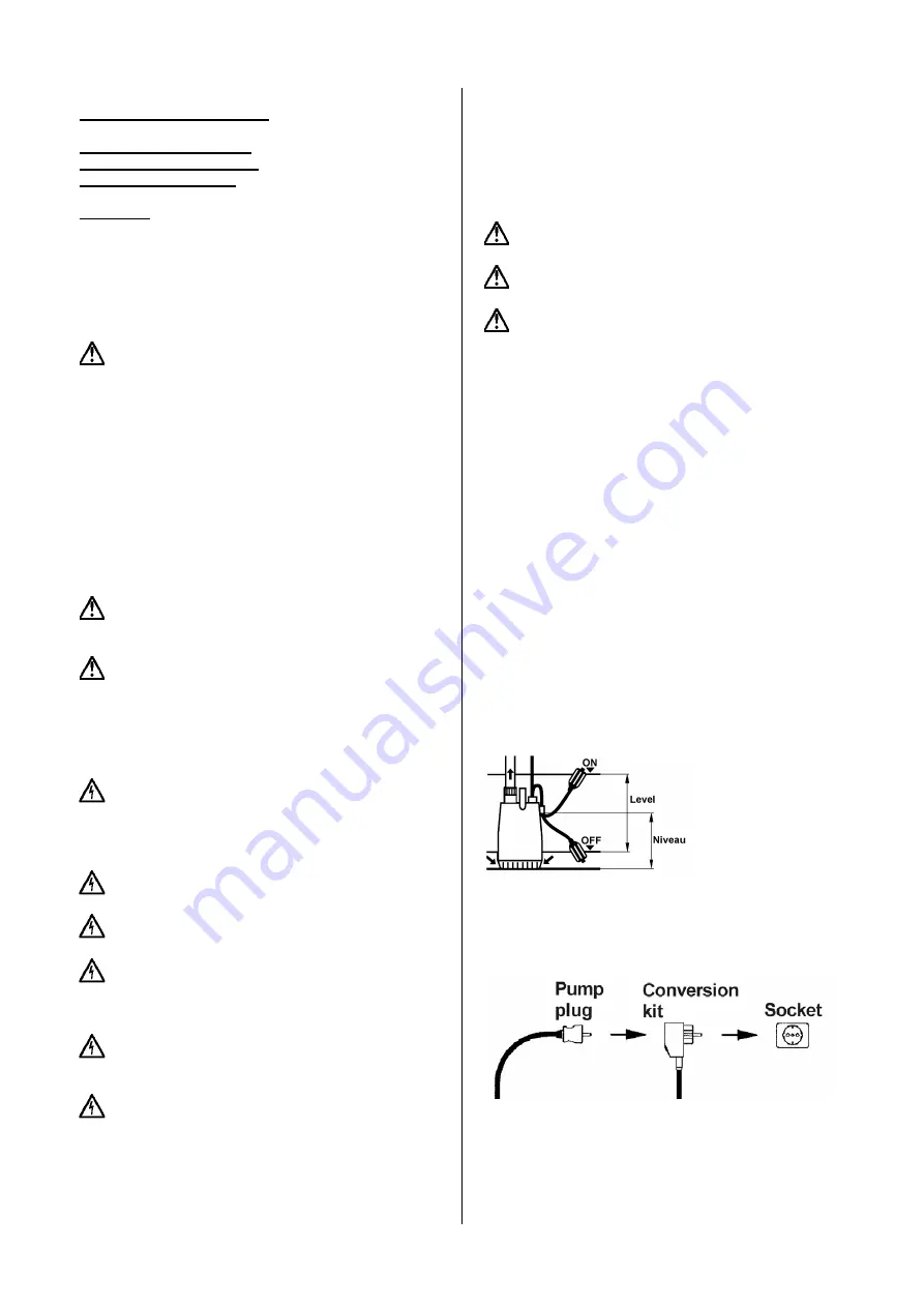
7.2. Automatic Float Switch Control
( only model CR 252 WA )
Pumps supplied with a float switch start and stop auto-
matically according to the liquid level in the pit automati-
cally.
Both the distance be-
tween start level (on)
and stop level (off) of
the pump and the
level of the fixing
point of the float
switch can be ad-
justed.
7.3. Automatic Float Switch Conversion Unit
Pumps without a float switch can be fitted with a float
switch conversion kit subsequently. Fit the conversion kit
between the mains supply and the pump plug.
When installing the conversion kit, never place the float
switch in the sump without fixing the float switch cable to a
fixed point in the sump, because for operation the float
switch must rotate around the fixing point of the cable.
Non-observance may cause an overflow (pump does not
start) or damage of the pump (pump does not stop).


