


Watchdog Timer
The Watchdog Timer is provided to prevent program malfunctions or sequences from jumping to
unknown locations, due to certain uncontrollable external events such as electrical noise. It oper-
ates by providing a
²
chip reset
²
when the WDT counter overflows. The WDT clock is supplied by
one of two sources selected by configuration option: its own self-contained dedicated internal
WDT oscillator, or the instruction clock (system clock divided by 4). Note that if the WDT configura-
tion option has been disabled, then any instruction relating to its operation will result in no opera-
tion.
The internal WDT oscillator has an approximate period of 65
m
s at a supply voltage of 5V. If se-
lected, it is first divided by 256 via an 8-stage counter to give a nominal period of 17ms. Note that
this period can vary with VDD, temperature and process variations. For longer WDT time-out peri-
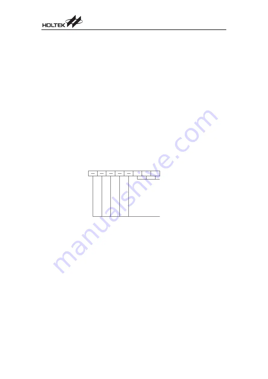
ods the WDT prescaler can be utilized. By writing the required value to bits 0, 1 and 2 of the WDTS
register, known as WS0, WS1 and WS2, longer time-out periods can be achieved. With WS0,
WS1 and WS2 all equal to 1, the division ratio is 1:128 which gives a maximum time-out period of
about 2.1s. The high nibble and bit 3 of the WDTS are reserved for user defined flags, which can
be used to indicate some specified status.
The WDT oscillator can be disabled and the WDT clock source can be supplied from the instruc-
tion clock (system clock divided by 4). If the instruction clock is used as the clock source it should
be noted that when the system enters the Power Down Mode, then the instruction clock is stopped
and the WDT will lose its protecting purposes. In such cases the system can only be restarted via
external logic. For systems that operate in noisy environments, the internal WDT oscillator is
strongly recommended.
Chapter 1 Hardware Structure
41
W S 2
W D T S R e g i s t e r
b 7
b 0
W D T p r e s c a l e r r a t e s e l e c t
W S 2
0
0
0
0
1
1
1
1
W S 1
0
0
1
1
0
0
1
1
W S 0
0
1
0
1
0
1
0
1
W D T R a t e
1 : 1
1 : 2
1 : 4
1 : 8
1 : 1 6
1 : 3 2
1 : 6 4
1 : 1 2 8
N o t u s e d , u s e r a c c e s s i b l e
W S 1 W S 0
Summary of Contents for HT48R05A-1
Page 7: ...vi Cost Effective I O Type MCU...
Page 8: ...P a r t I Microcontroller Profile Part I Microcontroller Profile 1...
Page 9: ...2 Cost Effective I O Type MCU...
Page 52: ...P a r t I I Programming Language Part II Programming Language 45...
Page 53: ...46 Cost Effective I O Type MCU...
Page 59: ...52 Cost Effective I O Type MCU...
Page 90: ...P a r t I I I Development Tools Part III Development Tools 83...
Page 91: ...84 Cost Effective I O Type MCU...
Page 101: ...94 Cost Effective I O Type MCU...
Page 104: ...Appendix Appendix 97...
Page 105: ...98 Cost Effective I O Type MCU...
Page 115: ...108 Cost Effective I O Type MCU...
Page 116: ...A p p e n d i x B Package Information Appendix B Package Information 109 B...
Page 123: ...116 Cost Effective I O Type MCU...
Page 125: ...Amendments...