


FM-ONE
HOKUTO DENSHI
CO;LTD;
株式会社
8
Target board
Prepare MCU-set board which is equipped with a specified write-in interface.
For the write-in interface and I/F circuit diagram of the interior FM
-
ONE, refer to attached
“User’s Guide.”
Connector and Cable
The connector model name and signal name are shown in the
“User’s Guide.”
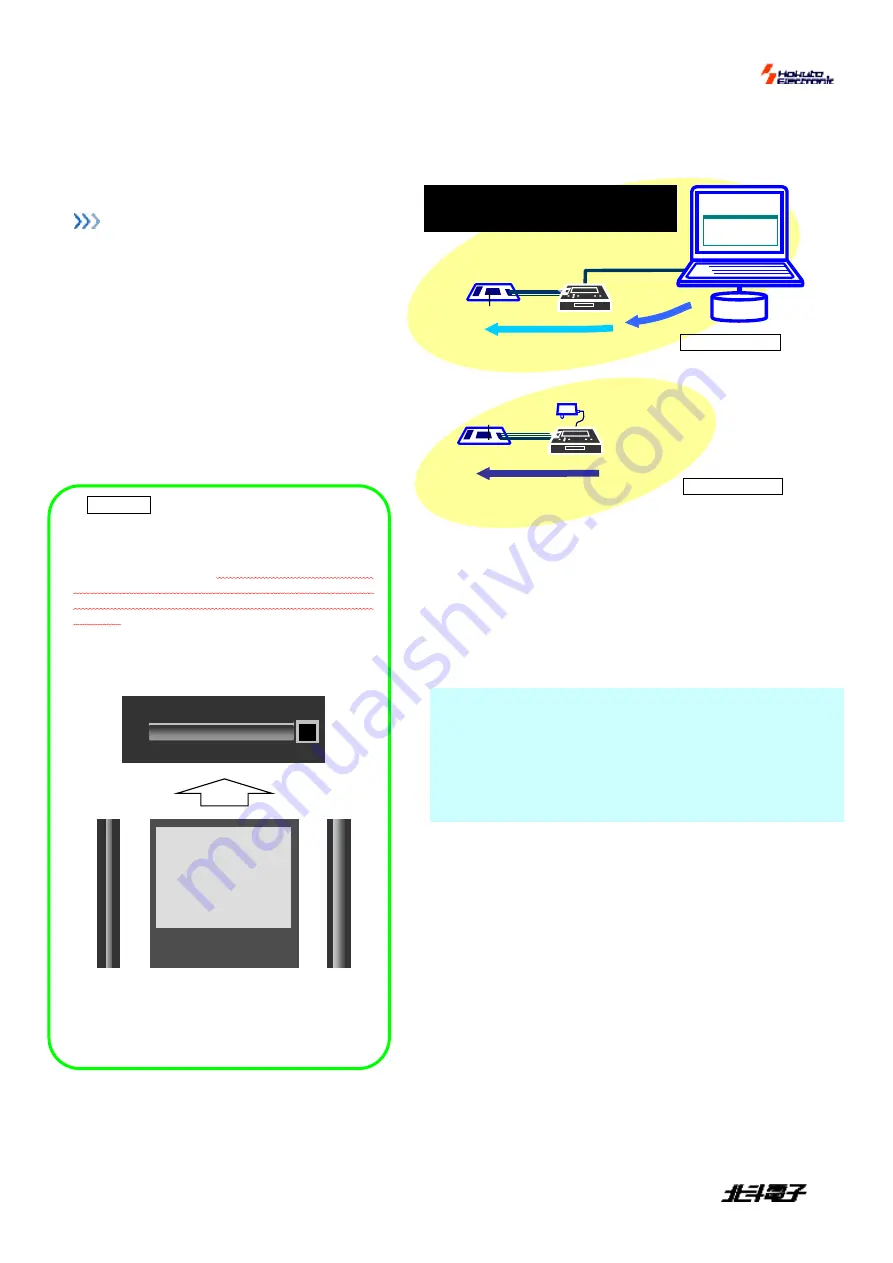
CONNECTION IMAGE
In using the
FM-ONE
, the target board,
FM-ONE
and PC must be connected as the diagram indicates,
on the right.
Prepare a target board according to our reference
circuit diagram, connect its write-in interface with the
FM-ONE
body with the target connection cable, and
then insert CF (Compact flash) through CF insertion
slot.
To connect the FM-ONE body with PC, you
must use a USB cable (not provided).
Power is to be supplied to the FM-ONE body
from a USB bus when PC is operated, or
otherwise from the attached adapter.
Cautions!
Insertion of CF
Insert CF with its back face upward.
A
slot is on the CF side.
Hold the CF card with the
wider slot to the right against the FM-ONE and the
narrower one to the left, and the back face will be
upward.
Insert the CF card until you hear click so that the
injection button will pop up.
RECOGNITION OF USB DEVICE OF CF
CF inserted into the FM-ONE body is recognized as a USB
storage by PC
.
Be sure to confirm if recognition is achieved properly
when a USB cable is connected and CF is inserted.
When a USB cable or CF is to be removed, be sure to cut
off the USB device.
USB
cable
From
PC to CF
MOT/HEX
P
P
C
C
ProjectFileMaker
ON-BOARD PROPGRAMMING BOOT MODE
Delete all of on-chip ROM, and then write the targeted
program.
Target board
Flash
on-chip microcomputer
F
M
-
O
N
E
Online operation
From
CF to on-chip
FlashROM
From
CF to on-chip
FlashROM
Target board
Flash
on-chip microcomputer
F
M
-
O
N
E
Attached AC adapter
or batteries
Offline operation
How to cut off USB device
Click on the removal icon in the task bar on the bottom-right of
Windows, and then cut off the
USB device
according to the
direction on the screen. Make sure if it is cut off, and then
remove the CF or the
USB cable. When “Disconnected USB”
is shown on the body display, it imust be disconnected properly.
Connection and disconnection can be done properly when PC is
not operating.
CF card
(
Back face
)
CF Card insertion slot
F
カード挿入口
L
e
ft
s
id
e
(n
a
rr
o
wer
fl
u
te
)
Rig
h
t
s
id
e
(wi
d
e
r f
lu
te
)
※
The card cannot be inserted with
the front face upward. Improper
insertion may damage the main
body.