0055
- 7
3 - SETTING UP
3.1 - SECURING
The machine can operate on any flat non-elastic surface.
Makes sure only the 2 support points (fig. 3) actually touch the floor.
If possible, we recommend securing the machine to the floor by means of the feet (see figure 3).
3.2 - POWER CONNECTIONS
The machine features a single phase and earth lead.
The power voltage (and mains frequency) is shown on the machine identification plate and cannot be
changed.
Mains connection must be done by expert personnel.
The machine must not be started until it is properly earthed
Connection to the power mains must be made using a slow-acting safety switch set at 2A (230V) or 4A
(115V).
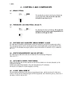
3.3 - PNEUMATIC CONNECTIONS (Model P)
To set up operation of the pneumatic clamping chuck (constant thrust gas-operated spring), connect the
wheel balancer to the compressed-air system. The connection fitting is on the rear of the wheel balancer.
At least 7 kg per sq cm (~ 7 MPa; ~ 7 BAR; ~ 100 PSI) are needed to ensure correct operation of the
release mechanism.
3.4 - FURTHER SAFETY DEVICES (MODEL P)
- Wheel always locked even in the event of a pressure break during the balancing cycle
- Rotating-block wheel clamping device to prevent the wheel coming off the flange in the event of
the pneumatic clamping pedal being accidentally pressed during the balancing cycle
Always operate the release control pedal when the machine is at a standstill, thereby preventing
abnormal flange stress and wear.
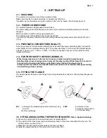
3.5 - FITTING THE FLANGE
The wheel balancer features a cone flange for securing wheels with centre hole. Other optional flanges can
be fitted:
Fig. 4
Fig. 4A
800
a) Remove the threaded end section A after removing
screw B.
b) Fit the new flange
800P
a) Unscrew rod B
b) Unscrew end section A
c) Fit the new flange
A
B
A
B
3.6 - FITTING AND ADJUSTING THE PROTECTION COVER
(Table 4 - Exploded drawings)
a) Secure the components to the bed as described in exploded table 4.
b) The position of the closed cover can be adjusted by means of the screw accessible from the rear. The
correct position is shown in Fig. 1
c) Make sure the microswitch is pressed when the cover is closed.
d) Adjust the angular position of the microswitch control (item 403).
Summary of Contents for Megaspin 800
Page 3: ...0055 3 ...


