background image

26

monty 3550 / 3550AIR

USA - CANADA

3.0-3

3.0-4

2

1062.tif

1053.tif

1052.tif

F.

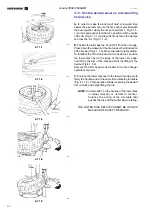
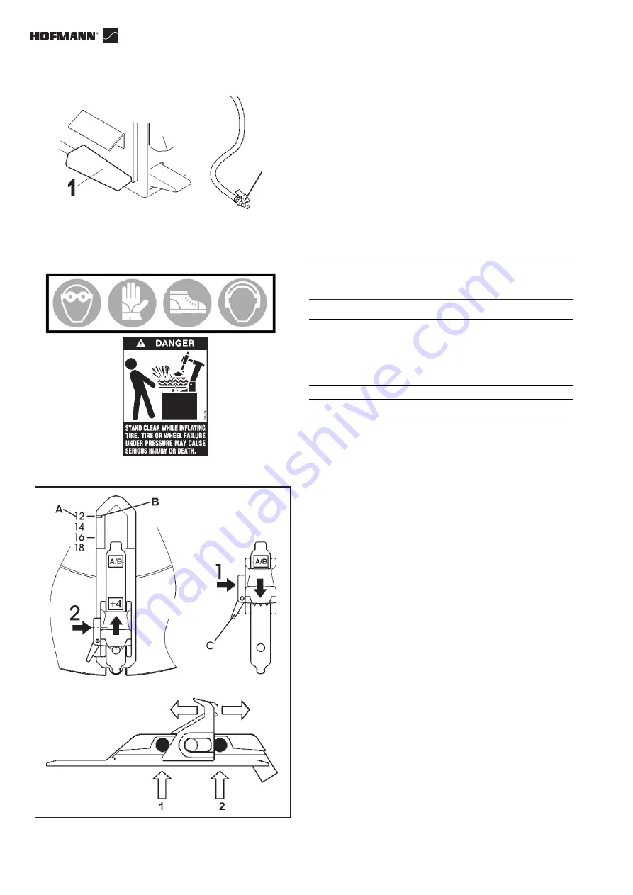
Press bead seater/inflator pedal on left side of the machine
down (

1

, Fig. 3.0-3): air will come from inflation hose end.

Only for Tubeless wheel models:

F1.   

Press bead seater/inflator pedal (

1

, Fig. 3.0-3) on left

side of the machine half way down: air will come from
inflation hose end only (

2

, Fig. 3.0-3).

F2.   

Press bead-seater pedal down swiftly to get air blast

from the inflator jets. Air simultaneously comes out of
inflator hose (

2

, Fig. 3.0-3).

Note:

 Air simultaneously continues to exit the hose

connected to the tire.

WARNING

:

ONCE BEADING IS COMPLETE, IMMEDIATELY STOP
INTRODUCING AIR.

WHEN OPERATING THE BEADING DEVICE IT IS
MANDATORY TO WEAR EAR PROTECTORS AND
SAFETY GLASSES TO PREVENT CONTAMINATION
FROM NOISE, DUST AND CHIPS BLOWN BY THE
AIR JET.

DANGER OF TIRE EXPLOSION

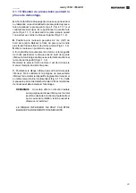
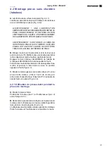
Presetting of clamping jaws:

H.

 The turntable jaws can be positioned in two different

way. Push the lever (

C

) on the left side of each jaw and

shift at the same each one (0/+4”) (Fig. 3.0-4).

N.B.:

 Turntable capacity can be changed before pedal

control.

VERY IMPORTANT:  LOOK FOR PROPER INSERTION
OF THE PIN

CAUTION! MAKE SURE ALL FOUR CLAMPING JAWS
ARE MOUNTED IDENTICALLY (1 OR 2, FIG. 3.0-4).
OTHERWISE THE RIM MAY COME LOOSE AND INJURE
THE OPERATOR!

Rim diameters are shown in inches on the turntable (A,
Fig. 3.0-4). The diameter setting (mark on jaw (B) must
coincide with mark on turntable) depends on the clamping
jaw position 1 or 2.

In jaws position 1 the diameter is preset directly

(1, Fig. 3.0-4).

In position 2 (2, Fig. 3.0-4) 4" must be added to the

diameter.

Summary of Contents for 3550 AIR

Page 1: ...rts list Notice d utilisation Liste des pièces détachées Electric pmeumatic pmeumatic tire changer for car light truck and motorcycle tires Démonte pneus électro pneumatique pneumatique pour roues de voitures ATV Moto Scooter et motocyclettes USA CANADA ...

Page 2: ...powaĪniony do zaáoĪenia skoroszytu technicznego o którym mowa w Zaáączniku VII litera A dyrektywy 2006 42 UE RUM Responsabilul Biroului Tehnic este autorizat sã întocmeascã dosarul tehnic prevãzut în anexa VII litera A din directiva 2006 42 CE privind echipamentele tehnice SLO Zodpovedný pracovník technického oddelenia je oprávnený vypracovaĢ technickú dokumentáciu podĐa prílohy VII þasti A Smerni...

Page 3: ...N DOCUMENTAZIONE FORNITA DOCUMENTACIÓN SUMINISTRADA DOCUMENTAÇÃO FORNECIDA EC DECLARATION EC DECLARATION CE CE KONFORMITÄTSERKLÄRUNG Wiring Diagram WD Schéma électrique Schaltplan Pneumatic Diagram PD Schéma pneumatique Pneumatikschema DICHIARAZIONE CE EC DECLARACIÓN CE DECLARAÇÃO CE Schema Elettrico WD Esquema Eléctrico Esquema Eléctrico Schema Pneumatico PD Esquema Neumático Esquema Pneumático C...

Page 4: ...Installation Page 18 2 3 Accessories Installation Page 18 2 3 1 Installing the Kit SLIDING JAW 4 INCH Page 18 2 3 2 IRAPID CHANGE OVER TOOL EXTENSION Page 20 3 0 Controls Page 24 4 0 Mounting And Demounting Precautions Page 28 4 1 Demounting Tubeless Tires Page 28 4 1 1 Use the bead presser as a Demounting Device Page 32 4 2 Mounting Tubeless Tires Page 34 4 2 1 Use the bead presser as a Mounting ...

Page 5: ...tage du Kit ÉTAU COULISSANT 4 POUCES Page 19 2 3 2 CHANGEMENTRAPIDEOUTILAEXTENSION Page 21 3 0 Commandes Page 25 4 0 Montage et Démontage Precautions générales Page 29 4 1 Démontage Pneus Sans Chambre tubeless Page 29 4 1 1 Presse talon pendant la phase de démontage Page 33 4 2 Montage Pneus Sans Chambre tubeless Page 35 4 2 1 Presse talon pendant la phase de montage Page 35 4 3 Enjantage du talon...

Page 6: ...ualified personnel Do not open any part of the unit other than noted and allowed areas Turn power switch off and unplug the unit before servicing Contact with high voltages can cause death or serious injury Risk of crushing Become familiar with all controls before proceeding with operation Stand away from the bead breaker arm when in operation Apply air to breaker in bursts if necessary to control...

Page 7: ...tion de service Le contact avec des hautes tensions peut causer la mort des dommages graves Risque d écrasement Se familiariser avec toutes les commandes avant toute utilisation Rester à distance de sécurité du bras de l outil de décollage pendant le fonctionnement Appliquer l air sur l outil de décollage par à coups si nécessaire pour contrôler la profondeur du bras Empêcher les personnes étrangè...

Page 8: ...an approved safety inflation cage designed for this purpose Lock turntable Clamp on inside of rim before attempting to inflate tire Use approved tire bead lubricant before removing or installing tire on rim ALWAYS position the Safety Restraint Arm over the wheel to hold it to the turntable while inflating if so equipped If a tire explodes on this tire changer STOP using it until the Safety Restrai...

Page 9: ...onflage de sécurité agréée et conçue à cet effet Bloquer la fixation de la plaque tournante à l intérieur de la jante avant de commencer à gonfler le pneu Utiliser un lubrifiant pour talon avant de démonter ou de monter le pneu sur la jante Placer toujours le bras de maintien de sécurité sur la roue pour la maintenir fixée à la plaque tournant pendant le gonflage en cas d équipement de ce genre Si...

Page 10: ...E THIS MANUAL IN A SAFE PLACE FOR FUTURE REFERENCE READ THIS MANUAL THOROUGHLY BEFORE USING THE MACHINE 1 1 Nomenclature Before installing and using the electric air tire changer it is suggested that you become familiar with the nomenclature of the machine s components Fig 1 1 1 1 Vertical slide 2 Mounting arm horizontally displaceable 3 Lever with push button 4 Handle 5 Mount demount tool 6 Tower...

Page 11: ...NSULTATION LIRE ATTENTIVEMENT CE MANUEL AVANT D UTILISER LA MACHINE 1 1 Terminologie Avant d installer et d utiliser le démonte pneus on conseille de se familiariser avec la terminologie de la machine Fig 1 1 1 1 Tige verticale 2 Bras de montage à déplacement horizontal 3 Levier avec bouton poussoir 4 Béquille 5 Outil 6 Potence 7 Autocentreur 8 Mors avec positionnement 9 Bras détalonneur 10 Palett...

Page 12: ... Motor 115 VAC kW 0 75 Hp 1 Max torque ftxlb 740 Nm 1000 Max wheel diameter 47 mm 1200 Max wheel width 17 Rim diam outside locking 12 26 Rim diam inside locking 14 28 Motorcycle wheels with adapters 10 25 1 3 Dimensions of the Machine Fig 1 3 1 1 4 Accessories Fig 1 4 1 EAA0247G02A Bead lifting tool EAA0247G05A Assembly Bottle EAA0304G16A Swab EAA0247G06A Insert for mounting head EAA0332G91A Slidi...

Page 13: ...ouple maximum 740 ftxlbs 1000 Nm Diamètre maxi de roue 47 mm 1200 Largeur maxi de roue 17 Blocage par l extérieur 12 26 Blocage par l intérieur 14 28 Blocage roues moto avec adaptaeurs 10 25 1 3 Dimensions de la machine Fig 1 3 1 1 4 Accessoires Fig 1 4 1 EAA0247G02A Levier soulève talon EAA0247G05A Groupe Réservoir EAA0304G16A Pinceau EAA0247G06A Inserts Outil EAA0332G91A KIT Étau Coulissant 4 po...

Page 14: ...EREDAREASINVITE ACCIDENTS H AVOIDDANGEROUSENVIRONMENTS DON TUSEPOWER TOOLS OR ELECTRICAL EQUIPMENT IN DAMP OR WET LOCATIONS OR EXPOSE THEM TO RAIN J KEEP THE WORK AREA WELL LIGHTED 1 5 1 Precautions THEUSEOFTHISDEVICEISALLOWEDONLYTOPERSONNEL DULYTRAINEDBYANAUTHORIZEDHOFMANNDEALER ANY MISUSE OR MODIFICATION OF THIS DEVICE OR OF ITS PARTS OR COMPONENTS NOT PREVIOUSLYAUTHORIZED BYTHEMANUFACTURERWAIVE...

Page 15: ...ORISENTLESACCIDENTS H ÉVITERLESSITUATIONSDANGEREUSES NEPASUTILISER D OUTILS PNEUMATIQUES OU ÉLECTRIQUES DANS DES LIEUX HUMIDES ET GLISSANTS NE PAS LES EXPOSERAUX INTEMPÉRIES J LAZONE DE TRAVAILDOIT ÊTRE BIEN ÉCLAIRÉE 1 5 1 Précautions L EMPLOI DE L APPAREIL EST PERMIS SEULEMENT AU PERSONNEL OPPORTUNÉMENT FORMÉ PAR LE DISTRIBUTEURAUTORISÉHOFMANN TOUTETN IMPORTEQUELCHANGEMENTOUMODIFICATION DE L APPA...

Page 16: ...binet Expansion screws 12x120mm shall be used Drill 12mm holes in the floor flush with the holes provided in the cabinet Place the nogs into the holes drilled in the floor and move the machine so that the holes of the cabinet are flush with the holes in the floor Tighten the screws at 70 Nm 51 ftxlb 2 1 Electrical Installation WARNING ALL ELECTRICAL CONNECTIONS SHALL BE PERFORMED BY A LICENCED TEC...

Page 17: ...our vis de 12x120 On doit faire des trous en correspondance des ouvertures prévues avec une perceuse avec un foret de 12 mm Ensuite introduire les chevilles et placer la machine en correspondance des trous ainsi préparés Introduire les vis et serrer avec une clé dynamométrique étalonnée à 70 Nm 51 ftxlb 2 1 Branchement électrique AVERTISSEMENT TOUTES LES INTERVENTIONS SUR L INSTALLATION ÉLECTRIQUE...

Page 18: ...ly with a rubber hose equipped with 3 8 NPT treaded junction WARNING BEFORE CONNECTING THE MACHINE TO THE AIR SUPPLY BE SURE ALL PERSONNEL ARE CLEAR OF THE MACHINE AND THAT NOTHING IS LEFT ON THE TURNTABLE AREA TOOLS B Should you install any optional accessories please refer to the relevant instructions 2 3 Accessories Installation 2 3 1 Installing the Kit EAA0332G91A SLIDING JAW 4 INCH KIT WARNIN...

Page 19: ...ir comprimé avec un tuyau en caoutchouc complet de cosse mâle avec filet 3 8 NPT AVERTISSEMENT AVANT DE RELIER LA MACHINE AU RÉSEAU DE L AIR COMPRIMÉ CONTRÔLER QUE RIEN NE SOIT LAISSÉ SUR L AUTOCENTREUR OUTILISETE B Si l on veut installer n importe quel accessoire en option il faut suivre les instructions de montage jointes 2 3 Installation de les accessoires 2 3 1 Montage du Kit EAA0332G91A KIT É...

Page 20: ... threaded ring nut C the washer 41x53x2 D and place the connection bush E on the hexagonal rod positioned so that the holes for the adjuster screws are facing upward and in line with the holes in the rod 5 Screw in the screw 10x20 G by hand without tightening also fitting the washer 10x32 H 6 Screw in the two screws F supplied in the kit by the same amount without tightening so that the bush remai...

Page 21: ... Figure 2 3 2 2 4 Mettre la bague filetée C la rondelle 41x53x2 D et montez la douille de fixation E sur la barre hexagonale en l orientant de façon à ce que les alésages des vis de réglage soient en haut et correspondent aux creux sur la barre 5 Vissez manuellement mais sans la serrer à fond la vis 10x20 G en interposant la rondelle 10x32 H 6 Vissez de la même façon sans serrer à fond les deux vi...

Page 22: ...he tool in this position Move the tool away from the edge of the rim then tighten the screw S Fig 2 3 2 3 under the tool fully home Installing and Adjusting the original tire changer tool See Figure 2 3 2 5 18 Fix the tool previously removed from the tire changer onto the second snap connection P2 supplied with the kit Repeat the installation operations in points 8 to 11 of these instructions 19 A...

Page 23: ...jante puis vissez à fond la vis S Fig 2 3 2 3 en dessous de l outil Montage et réglage de l outil original du démonte pneu Voir Figure 2 3 2 5 18 Fixez sur le second raccord rapide P2 fourni dans le kit l outil que vous avez démonté du démonte pneu Suivez les mêmes instructions que pour le montage du premier voir les points de 8 à 11 19 Procédez au réglage comme décrit aux points 14 et 15 20 Visse...

Page 24: ...rom the right the turntable turns clockwise 1 3 4 down approximately the turntable rotates at the minimum speed 8 rpm approx The torque is maximum in this condition 2 All the way down the turntable rotates at the maximum speed 14 rpm approx Lift the pedal and the turntable turns counter clockwise D Open the bead breaker arm Press down and hold WITH RIGHT FOOT the second pedal from the right by doi...

Page 25: ... tourner dans le sens des aiguilles d une montre 1 A peu près 3 4 en bas l autocentreur tourne au minimum de vitesse à peu près 8 t min La couple est au maximum 2 Tout en bas l autocentreur tourne au maximum de vitesse à peu près 14 t min En soulevant la pédale l autocentreur tournera sens inverse des aiguilles d une montre D Ouvrir le bras détalonneur Appuyer sans relâcher DU PIED DROIT sur la de...

Page 26: ...T IS MANDATORY TO WEAR EAR PROTECTORS AND SAFETY GLASSES TO PREVENT CONTAMINATION FROM NOISE DUST AND CHIPS BLOWN BY THE AIR JET DANGER OF TIRE EXPLOSION Presetting of clamping jaws H The turntable jaws can be positioned in two different way Push the lever C on the left side of each jaw and shift at the same each one 0 4 Fig 3 0 4 N B Turntable capacity can be changed before pedal control VERY IMP...

Page 27: ...IR POUVANT PROJETER IMPURETES ET POUSSIERES DANGER D EXPLOSION DU PNEU Préréglage des mors de serrage H Les mors de l autocentreur peuvent être positionnées de deux façons différentes Pousser le levier C sur le côté gauche de chaque mors et laissez les glisser de la même distance 0 4 Fig 3 0 4 NB la capacité de l autocentreur peut être changée avant d appuyer sur le pédale TRESIMPORTANT FAIREUNEBO...

Page 28: ...UBRICANT FOR TIRES F MAKE SURE THE TIRE IS THE CORRECT SIZE FOR THE RIM 4 1 Demounting Tubeless Tires A Remove all wheel weights from the rim Remove the valve stem or core and deflate the tire Fig 4 1 1 NOTE If the tire is over 13 340 mm wide first set the bead breaker in the Wide position as follow 1 Pull up and hold pin 1 Fig 4 1 2 and pull the bead breaker assembly in the Wide position 2 Releas...

Page 29: ...LEMENT UN LUBRIFIANT SPÉCIFIQUE POUR PNEUS F VÉRIFIER SI LE PNEU EST DE LA JUSTE DIMENSION POUR LA JANTE 4 1 Démontage pneus sans chambre tubeless A Enlever toutes les masses des bords de la jante Enlever la vanne et dégonfler le pneu Fig 4 1 1 REMARQUE Si le pneumatique est plus large de 13 340mm positionnez le détalonner dans la position Large de la manière suivante 1 Tirer et maintenir tiré l a...

Page 30: ... is necessary to avoid rim damage Fig 4 1 5 NOTE The plastic insert inside the mount demount tool must be periodically replaced Every machine is equipped with several plastic inserts inside standard equipment box If desired a steel roller also included in the standard equipment box may replace the plastic insert Follow the instructions included with the replacement parts NOTE Once the mount demoun...

Page 31: ...ge démontage doit être remplacé périodiquement Chaque machine est fournie de différentes pièces intercalaires de rechange dans la boîte des accessoires Si on le désire la pièce intercalaire en plastique peut être remplacée par une molette en acier contenue dans la boîte des accessoires Suivre les instructions jointes aux pièces de rechange REMARQUE Quand l outil de montage démontage a été correcte...

Page 32: ...ction of the tire bar Fig 4 1 1 3 Move the roller to rest position To facilitate the lift of the bead on the head tool position the lower disk next to the edge of the lower rim edge hold firmly the arm of the disk and start the lifting of the device Fig 4 1 1 4 Demount the first bead as described in the tire changer operator s manual C Position the lower disk next to the lower rim edge Hold firmly...

Page 33: ...lon sur la languette de l outil positionner le disque près du bord de la jante inférieure tenir la tige du disque avec fermeté et actionner la monté du dispositif Fig 4 1 1 4 Démonter le premier talon comme il est décrit dans le manuel d emploi du démonte pneu C Positionner le disque inférieur près du bord de la jante inférieur Tenir solidement la poignée du presse talon inférieur faire monter le ...

Page 34: ...demount tool is in the working position Engage the lower bead OVER the mounting wing and UNDER the mounting finger of the mounting tool Turn the wheel clockwise and push the tire down into the drop center opposite to the mount demount head Fig 4 2 3 C Mount the upper bead following the directions in section B Fig 4 2 4 With low profile tires the pneumatic bead holding and mounting tool Easymont Pr...

Page 35: ...re l outil en position de travail Engager le talon inférieur AU DESSUS de l ailette de montage et EN DESSOUS de la languette de l outil Faire tourner l autocentreur dans le sens des aiguilles d une montre et pousser le talon dans le creux en position opposée à l outil Fig 4 2 3 C Monter le talon supérieur de la même façon Pour les pneus taille baisse utiliser l outil de montage à actionnement pneu...

Page 36: ...E AND RIM CHECK FOR CORRECT SEALING BETWEEN THE VALVE AND THE FITTING AT THE END OF THE AIR HOSE AN AIR LEAK CAN GIVE INCORRECT PRESSURE READINGS AND CREATE SAFETY HAZARDS CHECK THAT THE READING ON THE PRESSURE GAUGE IS ZERO WHEN IT IS NOT IN USE THE COMPLETE SEATING THE BEAD ON THE RIM ISA VERY DANGEROUS STAGE OF THE TIRE MOUNTING PROCEDURE TO COMPLETE THE BEADING OPERATION AND INFLATE THE TIRE C...

Page 37: ...OLER L ETAT DU CAOUTCHOUC ET DE LA JANTE S ASSURER DE L ETANCHEITE ENTRE LE RACCORD DE LAVALVE ET L EXTREMITE DU TUBE D AIR COMPRIME UNE FUITE D AIR PEUT DETERMINER UNE LECTURE ERRONEE DE LA PRESSION ET UNE SITUATION DE DANGER VERIFIER SI L AIGUILLE DU MANOMETRE EST SUR ZERO EN CONDITION DE REPOS LA PHASE AU COURS DE LAQUELLE LE TALON VIENT PRENDRE PARFAITEMENT SA PLACE DANS LE LOGEMENT DELAJANTEE...

Page 38: ...1 down swiftly The top bead is already sealed by the lifting motion The air from the bead seater jets will rebound into the bottom sidewall driving it into place and creating a seal STOPTHE COMPRESSEDAIRAS SOONASTHE BEADS GRIP THE RIM WELL Place the wheel in a type approved cage to finish inflating and completely settle the beads in their seats on the rim Figure 4 3 3 WARNING WHEN OPERATING THE BE...

Page 39: ...é d air est expulsée par les injecteurs placés sur les griffes et le talon inférieur adhère au bord de la jante en permettant le gonflage ARRETER LA COMMANDE DES QUE LES TALONS ADHERENT PARFAITEMENTALAJANTE Placer la roue dans une cage homologuée pour procéder au gonflage et faire en sorte que le talon pénètre bien dans son logement sur la jante Fig 4 3 3 ATTENTION QUAND LE DISPOSITIF D ENJANTAGE ...

Page 40: ... After demounting the first bead remove the tube before demounting the second bead as described in section 4 1 5 1 Mounting tube type tires A Proceed as described in section 4 2 A Do NOT lubricate the tube Talc can be used to assist with the tube positioning B Mount the valve core and place the tube onto the tire to confirm that the tube is of the correct size Fig 5 1 1 C Inflate the tube slightly...

Page 41: ...E DE L OUTIL Après avoir démonté le premier talon enlever la chambre à air avant de démonter le deuxième talon comme décrit au 4 1 5 1 Montage pneus avec chambre A Opérer comme décrit au 4 2 A NE PAS lubrifier la chambre à air Si on le désire utiliser de la poudre de talc pour faciliter le positionnement de la chambre à air dans le pneu B Monter la vanne sur la chambre à air et l appuyer sur l env...

Page 42: ...stic parts with cold water and soap or window cleaner G Check the bead breaker pads Replace if worn H Discharge the water every day from air filter I The machine is equipped with an automatic lubricator Check the oil level weekly Fig 6 0 3 When adding oil to the lubricator disconnect the air supply first remove the fill screw A and add oil as needed Make sure seals are in place when repositioning ...

Page 43: ...ec du produit pour les vitres G Contrôler les supports du détalonneur et remplace si nécessaire H Vider l eau du filtre à air tous les jours I Lamachineestéquipéed unhuileurautomatique contrôler régulièrement le niveau de l huile Fig 6 0 3 Quand on ajoute de l huile au graisseur il faut tout d abord debrancher le réseau de l air comprimé enlever ensuite la vis A et ajouter de l huile en quantité s...

Page 44: ... time of disposal at the end of the lifetime of this equipment you must 1 NOT dispose of the equipment as municipal waste and separate collection is mandatory 2 Ask the retailer about collection points authorised for regular disposal 3 Stick to the standards for correct waste management to prevent potential effects on the environment and human health This symbol indicates that separate collection ...

Page 45: ...a vie de cet équipement il est obligatoire de 1 NE PAS ELIMINER cet appareillage comme déchet urbain mais d effectuer le tri sélectif de ses composants 2 S informerauprèsdurevendeursurlescentresdecollecte autorisés au tri et au traitement de ce type de déchet 3 Respecter les normes sur la gestion des déchets pour évitertoutrisqueprobabledenuisancesàl environnement et à la santé des personnes Ce sy...

Page 46: ...46 monty 3550 3550AIR USA CANADA Notes Blank Page for Blank Page pour Página en blanco para ...

Page 47: ...47 monty 3550 3550AIR USA CANADA Notes Blank Page for Blank Page pour Página en blanco para ...

Page 48: ...Phone 800 251 4500 Fax 501 450 2085 www hofmann usa com HOFMANN BALANCING TECHNIQUES LTD CANADA 6500 Millcreek Dr Mississauga Ontario L5N 4G4 Phone 800 267 2185 Fax 905 821 2073 www hofmann ca SOE Digital Code OM_MONTY3550 HNA_08 11_ZEEWH718A06_RA Release A ...

Reviews:

Related manuals for 3550 AIR