background image

hofflights.com

14

INSTALLATION MANUAL

IMH-104  v.01

PASCUA

All electrical work should only be undertaken after disconnection of the power by removing fuses or turning off the circuit 

breaker to ensure all pole isolation of the electrical supply.

Your fan is a drop rod fan in this situation the drop rod assembly is used to lower the fan down from it’s mounting position 

slightly. Extension rods, ranging from 30,5 cm (12”) to 183 cm (72”), are available if you need to lower your fan further. (This  

is normally the case in conservatories or rooms with very high ceilings.)

INSTALLING THE FAN

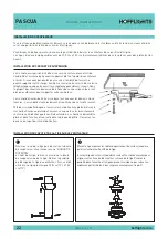
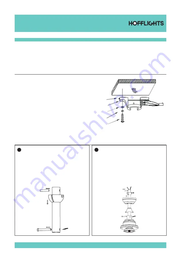
The hanger bracket should be screwed on to a firm flat surface. The fixing  

location must be able to withstand ten times the static weight of the fan. 

If you have any doubts as to the ability of your intended fixing location to 

be able to withstand this loading. Please contact our service help- line or 

another competent authority to advise you. In most situation two wood 

screws screwed into a wooden joist is more than adequate to support your 

ceiling fan.

The hanger bracket should be screwed onto the joist with the two wood 

screws provided. The washers provided should go in the following sequence:

Screw head > round washer > spring washer>Hanger bracket > Ceiling. 

Screw  the

hanger bracket to the ceiling and make sure all connections are secure to 

prevent the fan from falling. Fixings must screw into a joist and not just the 

plasterboard. Loosen the two canopy screws from the hanger bracket.

HANGER BRACKETINSTALLATION

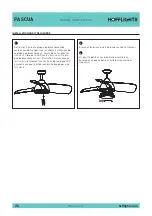
INSTALLING CANOPY AND DROP ROD ONTO THE FAN

1

Unscrew the screw on the drop rod hanger ball, then 

loosen the hanger ball. A “BALL PIN” will be  seen  on 

the drop rod, remove it and the hanger ball from the 

rod.

Remove the cotter pin and split pin from the drop rod 

boss of the fan. If a longer drop rod 30,5 cm (12”) to 183 

cm (72”), is going to be used transfer the ball joint and 

the earth wire to the longer rod.

2

Put the drop rod pass the electrical supply leads from the top 

of the motor through the drop rod until they exit at the top of 

the rod.

Insert the drop rod into the drop rod boss on top of the motor 

casing. Turn gently to align the holes in the boss with those 

in the rod. Ease the bolt pin through the boss and the rod 

taking care not to pinch or damage any cables. Fix in place by 

replacing the R-pin.

Summary of Contents for 5.0150.0211

Page 1: ...PASCUA MANUAL DE INSTALACIÓN INSTALLATION MANUAL MANUEL D INSTALLATION IMH 104 v 01 ...

Page 2: ......

Page 3: ...STRUCCIONES CON ATENCIÓN PARA GARANTIZAR UNA INSTALACIÓN SEGURA Y UN BUEN FUNCIONAMIENTO DEL VENTILADOR EN CASO DE DUDA CONSULTE A UN ELECTRICISTA CERTIFICADO CAUTION READ INSTRUCTIONS CAREFULLY FOR SAFE INSTALLATION AND FAN OPERATION IF UNSURE CONSULT A QUALIFIED ELECTRICIAN PRECAUTION LISEZ ATTENTIVEMENT LES INSTRUCTIONS POUR GARANTIR UNE INSTALLATION SÉCURISÉE ET LE BON FONCTIONNEMENT DU VENTIL...

Page 4: ... caja eléctrica indicada como siendo compatible con un soporte de ventilador y se deben usar los tornillos proporcionados en el cartón la mayoría de las cajas eléctricas que se usan habitualmente para el soporte de las luminarias no son compatibles para un soporte de ventilador y han de ser sustituidas Consulte a un electricista acreditado en caso de duda 7 Una vez completada la instalación contro...

Page 5: ...as importantes medidas e instrucciones de seguridad descritas en el manual no pretenden responder a todas las situaciones posibles que puedan ocurrir El sentido común y la prudencia son factores necesarios para la instalación y la puesta en marcha de este ventilador NOTA Este producto no debe ser usado por personas incluyendo a niños con capacidad física reducida capacidades sensoriales o mentales...

Page 6: ...o de la viga con los dos tornillos de madera proporcionados Las arandelas proporcionadas deben ser utilizadas en el siguiente orden Cabeza de tornillo arandela redonda arandela de resorte soporte de fijación techo Atornille el soporte de fijación en el techo y asegúrese de que todas las conexiones estén seguras para evitar cualquier caída del ventilador Las fijaciones deben ser atornilladas en la ...

Page 7: ...ijación A C Potencia de entrada del mando a distancia Marrón sobre marrón azul sobre azul verde amarillo sobre verde amarillo COLGAR EL VENTILADOR EN EL SOPORTE INSTALACIÓN DE LAS ASPAS 3 Apriete todos los tornillos en esta etapa Sirve para evitar que la tija y el ventilador se muevan el uno contra el otro También permite mantener un buen conducto detierra dentro del ventilador lo cual es importan...

Page 8: ...nes Monte y alinee el agujero detrás de la LED a tres agujeros de la placa de conexiones del motor ver dibujo Atornille a continuación firmemente del agujero de la LED por favor asegúrese de que el kit de luz no se mueva una vez atornillado 2 Conecte el conector del kit de luz y del ventilador 3 Atornille el kit de luz al cuerpo del ventilador Asegúrese de que la lámpara no esté demasiado apretada...

Page 9: ...porizador 5 Interruptor de luz Batería 12V 23A NOTA 1 Por favor espere unos instantes entre cada acción 2 Por favor manipule el transmisor con cuidado asegúrese de dejarlo caer o exponerlo al agua a mucha humedad o en un sitio cerca de una fuente de calor Una manipulación errónea puede provocar una avería y anular la garantía 3 El mando a distancia funcione con Radiofrecuencia por lo que no es nec...

Page 10: ...del ruido escuchando atentamente desde diferentes ángulos Aspas motor kit de luz etc El ruido del ventilador puede proceder del kit de luz 2 Asegúrese de que todos los tornillos de montaje del ventilador y del kit de luz estén bien apretados y correctamente enroscados De no ser así retírelos y vuélvalos a apretar Apriete estos tornillos al menos una vez al año porque pueden irse soltando poco a po...

Page 11: ...loque el medidor verticalmente contra el techo y contra el borde exterior de la aspa Note la distancia desde el borde de la aspa hasta el techo Gire despacio las aspas con precaución y manualmente para controlar las demás aspas Si la aspa sigue desalineada puede plegar ligeramente el soporte hacia arriba abajo para alinear la aspa con las demás Si después de seguir todas estas etapas el problema d...

Page 12: ...unting screws provided with the outlet box most outlet boxes commonly used for the support of lighting fixtures are not acceptable for fan support and may need to be replaced Consult a qualified electrician if in doubt 7 After installation is complete check that all connections are absolutely secure 8 After making electrical connections spliced conductors should be turned upward and pushed careful...

Page 13: ...ions and instructions appearing in the manual are not meant to cover all possible conditions and situations that may occur It must be understood that common sense and caution are necessary factors in the installation and operation of this fan NOTE This product is not intended for use by persons including children with reduced physical sensory or mental capa bilities are different or are impaired o...

Page 14: ...acket should be screwed onto the joist with the two wood screws provided The washers provided should go in the following sequence Screw head round washer spring washer Hanger bracket Ceiling Screw the hanger bracket to the ceiling and make sure all connections are secure to prevent the fan from falling Fixings must screw into a joist and not just the plasterboard Loosen the two canopy screws from ...

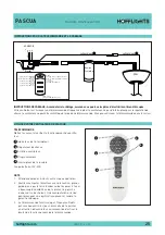
Page 15: ...rong Connect the push connector of hanging bracket to A C Input power of remote control Brownto brown blue to blue green yellow to green yellow HANGING THE FAN TO BRACKET INSTALLING BLADE 3 Tighten all set screws at this point This prevents the rod and the fan moving in relation to one and other It also assists in maintaining a good earth continuity through the fan which is important to the safety...

Page 16: ...plate Assemble and align the k hole on the back of Led light to the three screws on the connect plate of motor please see the picture Then screw the three screws tightly from hole on the LED plate please make sure the light kit can t be moved after screwing 2 Connect the push plug from light kit and fan 3 Screw lamp shade into fan housing Make sure lamp shade is secure but not overly tight ...

Page 17: ...or switch 12V 23A NOTE 1 Please allow a moment between each operation 2 Please handle the transmitter with care be sure not to drop or expose it to water high humidity or place whe re is too close to a heating element Improper handling may result in malfunction and voidthe warranty 3 The remote control is operated by Radio Frequency so it won t be Necessary to point this unit at the ceiling fan wh...

Page 18: ...ing noise 4 Make sure the light kit is securely fastened to the fan and all glass screws are finger tightened only Do not tighten with pliers or a screw driver 5 Make sure mounting bracket is installed snugly to junction box 6 Make sure wire nuts in switch housing or canopy are not rattling against each other or against wall of housing Wrap with electrical tape if necessary 7 Make sure the canopy ...

Page 19: ...d against the outsi deleading edge of a blade Note thedistance of the edge of blade to the ceiling Carefully turn the blades slowly by hand to check the remaining blades If the blade is not in alignment theblade holder may be gently bent up or down to be in line withtheother blades After followingallthestepsandifthewobblingproblemisnotsolved a dynamic balancing needs to be done by balancing kit Fo...

Page 20: ...le boîtier électrique indiqué comme étant compatible avec un support de ventilateur et utilisez les vis fournies dans la boîte La plupart des boî tiers qui servent à fixer les luminaires ne sont pas compatibles avec le support de ventilateur et il se peut que celles ci doivent être changées En cas de doute consultez un électricien qualifié 7 Une fois l installation terminée vérifiez que tous les b...

Page 21: ...curité du mode d emploi ne peuvent en aucun cas couvrir toutes les conditions et situations qui peuvent se présenter Par conséquent le bon sens et les précautions sont des éléments nécessaires pour l installation et le fonctionnement de ce ventilateur NOTE Ce produit ne doit pas être manipulé par des personnes y compris les enfants aux capacités physiques réduites ou aux capacités mentales différe...

Page 22: ...chet de fixation doit être vissé dans la solive avec les deux vis à bois fournies Les rondelles fournies doivent être utilisées dans l ordre suivant Tête de vis rondelle bague à ressort crochet de fixation plafond Vissez le crochet de fixation au plafond et assurez vous que tous les branchements sont sûres afin d éviter que le ventilateur tombe Les fixations doivent être placées dans la solive et ...

Page 23: ...âbles est erronnée Branchez le connecteur du crochet de suspension A C Alimentation électrique de la télécommande Marron sur marron bleu sur bleu vert jaune sur vert jaune SUSPENDRE LE VENTILATEUR AU SUPPORT INSTALLATION DES PALES 3 À ce stade serrez toutes les vis Cela évitera que la tige et le ventilateur bougent l un par rapport à l autre Cela permet aussi de garder un bon conducteurde terre da...

Page 24: ...Assemblez et alignez les trous à l arrière de la LED sur les trois vis sur la pla que de branchement voir illustration Serrez ensuite les trois vis fermement sur les trous de la plaque LED assurez vous que le kit de lumière ne bouge pas une fois vissé 2 Branchez les prises du kit de lumière et du ventilateur 3 Vis pour l abat jour sur le boîtier du ventilateur Assurez vous que l abat jour est bien...

Page 25: ... de la lumière Coupe batterie 12V 23A NOTE 1 Attendez quelques instants entre chaque opération 2 Veuillez manipuler l émetteur avec précaution prenez garde de ne pas le faire tomber ou de l exposer à l eau à beaucoup d humidité ou de le placer trop proche d une source de chaleur Une manipulation erronée peut provoquer une dysfonctionnement et rendre la garantie caduque 3 La télécommande fonctionne...

Page 26: ...oquer un cliquètement 4 Assurez vous que le kit de lumière est correctement fixé au ventilateur et que toutes les vis du verre sont serrées uniquement manuellement Ne serrez pas avec des pinces ou un tournevis 5 Assurez vous que le support de fixation est bien installé sur le boîtier de raccordement 6 Assurez vous que les écrous du boîtier d interrupteur ou du capot ne se cognent pas entre eux ou ...

Page 27: ...e Placez l indicateur contre le plafond verticalement et contre la face externe de la pale Notez la distance entre le bord de la pale et le plafond Tournez lentement les pales avec précau tion à la main pour vérifier les pales restantes Si la pale n est pas alignée vous pouvez courber légèrement le support de pale vers le haut ou vers le bas pour l aligner avec par rapport aux autres Après avoir s...

Page 28: ...C dels Oficis n 25 Pol Ind el Regàs 08850 Gavà Barcelona Spain T 34 93 630 28 00 M info hofflights com hofflights com PASCUA IMH 104 v 01 by ...

Reviews: