WWW.HOBBYEAGLE.COM 4 / 16
RECEIVER CONNECTION
Standard PWM Receiver
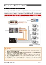
When using a standard PWM receiver, A3S4 has 7 input channels in which at least one channel should
be connected to the receiver in
Aileron (A), Elevator (E) and Rudder (R),
or the gyro will enter the receiver
timeout mode (Red Slow Flashing). The descriptions of input channels are shown in the following table.
A
E
R
A2
E2
G
Serial RX/M
AIL
ELE
RUD
AIL2
ELE2
Remote Master Gain
Serial RX Input / Flight Mode
NOTES
[
Serial RX/M
] is used for flight mode switching, use a 3-position switch of the transmitter to
switch the flight mode during flight.
[
G
] is used for remote master gain control, a slide lever or a switch of the transmitter can be
used to tune or change the master gain during flight.
Connect the ESC or the throttle servo to the receiver directly without passing through the gyro.
Pins on slot [
A-E-R
] and [
A2-E2-G
] are only used as signal input pins, NEVER connect a power
source on these pins.
Pay attention to the polarity of the plugs. The orange signal line must always be on the top and
the brown on the bottom.


