background image


WWW.HOBBYEAGLE.COM                                                                                                                        1  /  16 


4


User Manual


V1.0    Mar, 2022 Revision 


Summary of Contents for A3 SUPER 4

Page 1: ...WWW HOBBYEAGLE COM 1 16 4 User Manual V1 0 Mar 2022 Revision...

Page 2: ...scope calibration keep the airplane stationary after power on and wait while the LED flashes blue The LED will stay solid blue if a slight movement is detected and the calibration will not start until...

Page 3: ...ires as possible Mounting Orientation Use one of the supplied double sided tapes to attach the gyro to the airplane firmly For best performance the gyro should be mounted as close to the C G as possib...

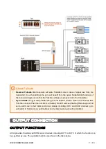
Page 4: ...erial RX Input Flight Mode NOTES Serial RX M is used for flight mode switching use a 3 position switch of the transmitter to switch the flight mode during flight G is used for remote master gain contr...

Page 5: ...order After each time you have changed the receiver type the current channel settings will be reset to the default Choose None for those channels you do not use Table 1 Serial Receiver Protocols Supp...

Page 6: ...ys be on the top and the brown on the bottom A special optional adapter is required if you want to use a Spektrum satellite remote receiver Spektrum DSM2 X Satellite Receiver By using the DSM Adapter...

Page 7: ...provides the gyro level Failsafe function when the connection fails from the receiver When the function is activated the LED will keep flashing Red slowly and all servos will move to their initial po...

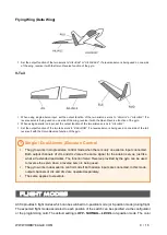
Page 8: ...used on one side of the wing In this case the Servo Reverse function provided by the gyro makes it easy to change the direction of one of the servos The same also applies to such applications as two e...

Page 9: ...rse function of the gyro Single Dual Aileron Elevator Control The gyro works in single aileron control mode when there is only one aileron input connected Both output channels of AIL and AIL2 issue th...

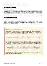
Page 10: ...airplanes It can effectively improve the stability and precision of the airplane and reduce the stall point specially 3 LOCK Mode The LOCK mode is also known as the Attitude Lock mode 3D mode or AVCS...

Page 11: ...n nose up and keeps hovering This mode is designed to help you to learn hovering maneuver and reduce the probability of crashing Setup of Flight Mode Switch You can use any 3 position switch of the tr...

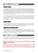
Page 12: ...e tune the basic gain until you get the best performance Mode Gain Furthermore the gyro gain of each axis can also be adjusted separately for each flight mode including Lock Gain Angle Gain Level Gain...

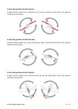
Page 13: ...ected directions as shown below Check the gyro direction for Elevator Quickly rotate the airplane up or down around the pitch axis the elevator should react in the expected direction as shown below Ch...

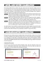
Page 14: ...get a rapid red blinking during calibration this means the result exceeds the maximum permissible value i e 25deg in this case you have to re install the gyro to reduce the deviation caused by install...

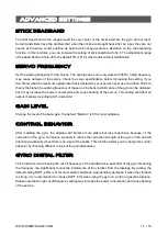
Page 15: ...but it may increase the power consumption and cause heating of the servos This setting will affect all output channels including AUX1 and AUX2 Gain Level Change the level of the basic gain the default...

Page 16: ...df Quick Start Guide https www hobbyeagle com a3 configurator docs quick_start_guide_en pdf Firmware Update Guide https www hobbyeagle com a3 configurator docs firmware_update_guide_en pdf VERY IMPORT...

Reviews: