


16
C
hannel
1 (e
levator
), C
hannel
2 (a
ileron
),
and
C
hannel
4 (r
udder
)
operate
independently
.
t
his
option
is
used
on
airCraft
that
feature
a
separate
wing
,
horizontal
stabilizer
,
and
vertiCal
fin
.
C
hannel
1 (e
levator
)
and
C
hannel
4 (r
udder
)
are
M
ixed
and
operate
together
. t
his
option
is
used
on
airCraft
that
feature
a
v-t
ail
instead
of
a
separate
stabilizer
and
vertiCal
fin
. t
his
setup
is
CoMMon
on
Many
sailplanes
and
gliders
.
C
hannel
1 (e
levator
)
and
C
hannel
2 (a
ileron
)
are
M
ixed
and
operate
together
. t
his
option
is
used
on
delta
airCraft
or
flying
wings
that
don
'
t
feature
a
separate
horizontal
stabilizer
.
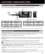
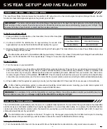
cOnTROL FUncTiOnS
SERvO REvERSing
The Servo Reversing function electronically switches the direction of servo travel. For example, if you pull the elevator control stick
back for Up elevator, but your elevator moves Down, you can use the Servo Reversing function to switch the direction of servo travel
to make the elevator move Up. Servo Reversing options can be changed for channels 1 through 4 independently.
Changing Servo Reversing Options
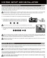
1) To change the direction of servo travel for the desired channel, move the Servo
Reversing switch for that specific channel either Up or Down.
CH1
- Elevator
CH2
- Aileron
CH3
- Throttle
CH4
- Ruder
channEL Mixing
The Channel Mixing function allows you to quickly set up the transmitter's low-level mixing based on the type of aircraft you're flying.
Options include Normal, Delta (Elevon), and V-Tail. For example, if you're setting up an aircraft that uses Elevons, you can choose
Delta to automatically setup the correct elevator and aileron Mixing.
OPTION
OPTION NAME
OPTION DESCRIPTION
norMal
v-tail
delta
n
orMal
(n
o
M
ixing
)
v-t
ail
M
ixing
d
elta
(e
levon
) M
ixing
The following Channel Mixing options are available:
For reference, when the Servo Reversing switches are Down, this is considered
the 'Normal' position and when the Servo Reversing switches are Up, this is considered the 'Reverse' position.
Changing Mixing Options
1) To change the Mixing option, move the Mixing switch adjacent to the Mixing Type
desired.
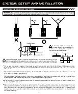
Although the Mixing switch is recessed to prevent accidental movement, check the position of the Mixing switch and the movement
of your aircraft's control surfaces prior to flight to ensure correct operation for the aircraft you're flying. In addition, DO NOT move
the Mixing switch during flight!
Although the Servo Reversing switches are recessed to prevent accidental movement, check the position of the Servo Reversing
switches and the movement of your aircraft's control surfaces prior to flight to ensure correct operating for the aircraft you're
flying. In addition, DO NOT move the Servo Reversing switches during flight!
Summary of Contents for Aero Sport 5
Page 1: ...1...


