Hobbico Hobbistar 60 Select Instruction Manual Download Page 12

ENGINE INSTALLATION

1. Temporarily install the two mounting pads to the engine mount using

four 4mm x 15mm screws. Set the engine on the mounting pads so

that the center line of the engine is in line with the center line of the
engine mount. Also the drive washer on the engine must protrude

1/8" from the front of the plane. Next, mark the mounting holes for

the engine on the pads.

2. Remove the pads and drill a 5/32" hole at each mark.

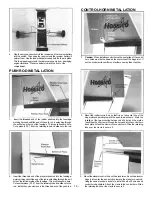
4. Make a "z" bend in the 17 3/4" throttle control rod and install on the

throttle arm of engine. Next, cut one white tube so it is 9" long. Rough
it up slightly with sand paper. Now epoxy it inside of the fire wall and
to the fuselage former as shown (You may have to drill the hole
completely through the firewall).

5. As you install the engine and mounting pads on the engine mount,

slide the throttle control rod into the throttle control tube. Install the
four lock washers. Note: It is advisable to use semi permanent

thread locking compound on the screws.

ASSEMBLY OF FUEL TANK

3. Mount the engine to the mounting pads by using four 4mm x 15mm

screws, four lock washers and four 4mm nuts (small) as shown.

1. Assemble the fuel tank as shown. Apply a bead of silicone sealant

around the fuel tank cap as shown when installing it into the fuselage.

- 1 2 -

Summary of Contents for Hobbistar 60 Select

Page 1: ...ARE FACTORY ASSEMBLED FOR PERFECT ALIGNMENT AND QUICK ASSEMBLY ALL PRE ASSEMBLED COMPONENTS ARE FACTORY COVERED CLASSIC DESIGN WITH DURABLE BALSA AND PLYWOOD CONSTRUCTION SEMI SYMMETRICAL AIRFOIL GIV...

Page 2: ...stypeand will offeryou many hours of enjoyment ADDITIONAL ITEMS Please check the additional items listed below for those materials not furnished but recommended Dubro 163 Wing seat tape 1 Dubro 121 E...

Page 3: ...5 Throttle and nose gear control rods 17 3 4 2 26 Plastic guide tubes 2 27 Clevis 4 28 Control horns 2 29 Control horn back plate 2 30 4mm x 10mm collars 3 31 m3 x4 screw 7 32 Nose gear control horn 1...

Page 4: ...ine along the hingepointonboth sides of the hinge This will preventepoxy from getting in the hinge joint and ruining the hinge Do not get vaseline on the rest of the hinge Ifthishappenstheepoxywillnot...

Page 5: ...it the aileron on the wing Be surethe torque rod fitsinthe hole in the edge oftheaileron The torque rod is what will transmit motion from the servo to theaileron 11 Install the rudder on the vertical...

Page 6: ...o cure 2 Slide the other wing panel onto the wing joiner Slide the two wing halves together Check for proper alignment There should be no gap between the wing halves If there is trim the end of the wi...

Page 7: ...sly measured in Step 1 1 Locate the pre assembled 21 aileron servo tray with 42 balsa blocks and a servo from your radio system Slip the servo into the tray and measure the distance from the bottom of...

Page 8: ...right when viewing the plane from the tail The area appears slightly darker Remove the covering from this area at this time 8 The elevator exit hole is located on the left side of the fuselage 61 2 f...

Page 9: ...ines Thiswillallowa more secure glue jointwhenthestabilizerisepoxyedlater Donotcutthebalsawood under the covering 3 Locate the vertical stabilizer Remove the covering from the lower vertical stabilize...

Page 10: ...o the center line of the fuselage 1 Looking into the fuselage vertical stabilizer slot apply some epoxy to the topsurface of the horizontal stabilizer that is visible inside the fuselage 2 Mix a small...

Page 11: ...ar control horn parallel to the nose gear axle and tightenthemountingscrew Nextinstalla4mmx 10mmcollarontop ofthe control horn and secure with a m3 x 4 screw 1 1 3 If usingthe Snap R Keeper make a 90...

Page 12: ...gine Next cutonewhitetubesoitis9 long Rough itupslightlywith sand paper Nowepoxy it insideofthe firewall and to the fuselage former as shown You may have to drill the hole completely through the firew...

Page 13: ...fuselage as viewed from abovelookingtowardtheengine and2 downfromthewingsaddle Install the switch at this time Mounting the switch on this side will preventfuel from damaging the switch 2 Test fit yo...

Page 14: ...etaining tube and slide onto the rod 2 Mount the ruddercontrol horn so that it is on the center line of the hinge joint and pointing toward the push rod as shown Mark the location of the two mounting...

Page 15: ...nd adjusted 5 Make a 90 bendat the markon the push rods Cutthe excesswire asshown andinstalltheSnap R Keeperstothe rodandservoarms following the manufacturer s instructions If using E Z connectors ins...

Page 16: ...connected to the receiver otherwise thewingwill need to be removed later to connect it The wing ismountedto thefuselage byusing 8 64 rubberbands Wrapthe bands around the wooden dowels as shown above...

Page 17: ...e carburetor while turning the prop counter clockwise a few time Notice the fuel line It no fuel is reaching the carburetor recheck the fuel line plumbing 6 Reduce the throttle to 1 4 or 1 2 throttle...

Page 18: ...the wind and slowlyadvance the throttle uptofull throttle Atthis pointthe planewill be going very fast and will be very sensitive to your rudder inputs Use smoothinputstocorrecttheplanefromwanderingof...

Page 19: ...gained speed gently pull back on the elevator stick Do not allow the plane to climb too steeply 8 Keepthewingsleveland reducethe throttle sometoobtain agentle climb 9 Toturn gentlymovetheaileron stick...

Page 20: ...ASAP AIRPLANE KITS HCAA2580 Telstar 40 HCAA2520 Telstar 25 HCAA2050 Flightstar 40 HCAA2530 Cherekee 25 HCAA2600 Extra 300 HCAA2590 Cessna 182 20 Entire contents 1990 Inc...

Reviews: