


OM-498 Page 12
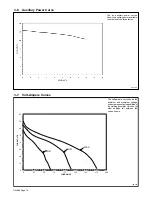
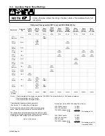
3-6.
Auxiliary Power Curve
802 129
The ac auxiliary power curves
show the auxiliary power available
in amperes at the receptacles.
3-7.
Volt-Ampere Curves
198 453
The volt-ampere curve shows the
minimum and maximum voltage
and amperage output capabilities of
the welding generator. Curves of all
other settings fall between the
curves shown.
0
10
20
30
40
50
60
70
80
0
25
50
75
100
125
150
175
200
LOAD AMPS
LOAD VOL
TS
MIN
MID
MAX
Summary of Contents for 1435
Page 4: ......
Page 35: ...OM 498 Page 31 198 014 C Figure 9 2 Wiring Diagram For Welding Generator ...
Page 36: ...OM 498 Page 32 201 026 A Figure 9 3 Wiring Diagram For Auxiliary Power Panels 1 Of 2 ...
Page 37: ...OM 498 Page 33 201 026 A Figure 9 4 Wiring Diagram For Auxiliary Power Panels 2 Of 2 ...
Page 53: ...OM 498 Page 49 Notes ...
Page 58: ...OM 498 Page 54 Notes ...