OM-230 261 Page 19
S
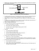
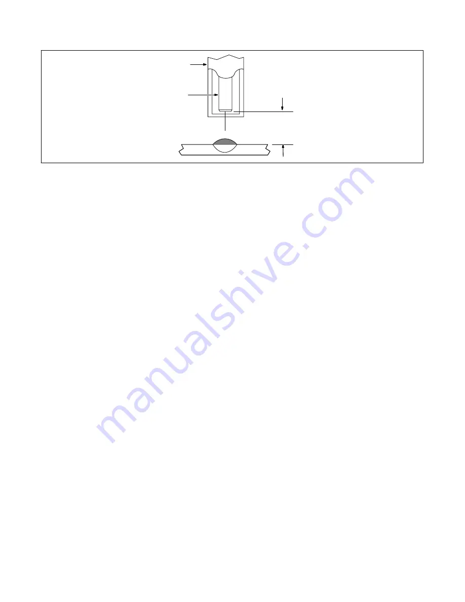
Maintain a 3/4 in. (19 mm) tip-to-work distance, and have the contact tip recessed approximately 1/8 in. inside the
nozzle if possible. See Figure 5-2.
ÇÇÇÇ
ÇÇÇÇ
ÇÇÇÇ
ÇÇÇÇ
ÇÇÇÇ
ÇÇÇÇ
ÉÉÉ
ÉÉÉ
Gas Nozzle
Contact Tube Recessed 1/8
in. (3.2 mm) Inside The Nozzle
Contact Tip To Work
Distance 3/4 in. (19 mm)
Figure 5-2. Contact Tube Position And Tip-To-Work Distance
S
Avoid large weave beads on aluminum. If larger fillet welds are needed, multiple pass straight beads will provide
better appearance and have less chance of cold lapping, burn through, and other weld defects.
S
It will be necessary to increase torch travel speed as the base material becomes heated during the welding
process.
S
The skill level of the operator, joint types, fit up, and positions, as well as the welding power supply will all have a
great influence on the weldability of the aluminum and your success.
C. Common Problems/Troubleshooting
S
Burn through (melt through) caused by over heating the base material.
1.
Increase travel speed. Make shorter welds.
2.
Move around on part, spreading out the heat.
3.
Use thicker material, change joint design or welding process to AC TIG.
4.
Eliminate or reduce gaps.
S
Dirty welds.
1.
Use push angle instead of drag technique.
2.
Increase voltage to get into spray transfer.
3.
Use proper base metal cleaning techniques (stainless steel brush).
4.
Check for proper shielding gas and wire alloy type.
S
Wire burns back to contact tip during or at the end of the weld.
1.
Maintain a 3/4 in. (19 mm) tip-to-work distance.
2.
Check to make sure the contact tip size, drive rolls and gun liner match the wire diameter that you are using.
(Sometimes an oversized tip can be used. The ID should only be one size larger than the wire diameter.)
S
Wire “bird nests” (piles up) in front of inlet guide on gun.
1.
Check and adjust drive roll tension.
2.
Check to make sure drive rolls match wire diameter.
3.
Replace contact tip if fouled or plugged.(Sometimes an oversized tip can be used. The ID should only be one
size larger than the wire diameter.)
Summary of Contents for 3545-20
Page 4: ......
Page 14: ...OM 230 261 Page 10 ...
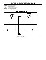
Page 24: ...OM 230 261 Page 20 SECTION 6 ELECTRICAL DIAGRAMS Figure 6 1 Circuit Diagram 186 451 ...
Page 25: ...OM 230 261 Page 21 Notes ...
Page 28: ...Notes ...
Page 29: ...Notes ...
Page 30: ...Notes ...


