background image

TABLE OF CONTENTS

SECTION 1 

 SAFETY PRECAUTIONS - READ BEFORE USING

1

. . . . . . . . . . . . . . . . . . . . . . . . . . . . . . . . . 

1-1. Symbol Usage

1

. . . . . . . . . . . . . . . . . . . . . . . . . . . . . . . . . . . . . . . . . . . . . . . . . . . . . . . . . . . . . . . . . . . . . . . 

1-2. Arc Welding Hazards

1

. . . . . . . . . . . . . . . . . . . . . . . . . . . . . . . . . . . . . . . . . . . . . . . . . . . . . . . . . . . . . . . . . 

1-3. Additional Symbols For Installation, Operation, And Maintenance

3

. . . . . . . . . . . . . . . . . . . . . . . . . . . . 

1-4. California Proposition 65 Warnings

4

. . . . . . . . . . . . . . . . . . . . . . . . . . . . . . . . . . . . . . . . . . . . . . . . . . . . . . 

1-5. Principal Safety Standards

4

. . . . . . . . . . . . . . . . . . . . . . . . . . . . . . . . . . . . . . . . . . . . . . . . . . . . . . . . . . . . 

1-6. EMF Information

4

. . . . . . . . . . . . . . . . . . . . . . . . . . . . . . . . . . . . . . . . . . . . . . . . . . . . . . . . . . . . . . . . . . . . . 

SECTION 2 

 CONSIGNES DE SÉCURITÉ 

 LIRE AVANT UTILISATION

5

. . . . . . . . . . . . . . . . . . . . . . . . . . 

2-1. Symboles utilisés

5

. . . . . . . . . . . . . . . . . . . . . . . . . . . . . . . . . . . . . . . . . . . . . . . . . . . . . . . . . . . . . . . . . . . . 

2-2. Dangers relatifs au soudage à l’arc

5

. . . . . . . . . . . . . . . . . . . . . . . . . . . . . . . . . . . . . . . . . . . . . . . . . . . . . 

2-3. Dangers supplémentaires en relation avec l’installation, le fonctionnement et la maintenance

7

. . . . . 

2-4. Proposition californienne 65 Avertissements

8

. . . . . . . . . . . . . . . . . . . . . . . . . . . . . . . . . . . . . . . . . . . . . . 

2-5. Principales normes de sécurité

9

. . . . . . . . . . . . . . . . . . . . . . . . . . . . . . . . . . . . . . . . . . . . . . . . . . . . . . . . . 

2-6. Informations relatives aux CEM

9

. . . . . . . . . . . . . . . . . . . . . . . . . . . . . . . . . . . . . . . . . . . . . . . . . . . . . . . . 

SECTION 3 

 INSTALLATION

11

. . . . . . . . . . . . . . . . . . . . . . . . . . . . . . . . . . . . . . . . . . . . . . . . . . . . . . . . . . . . . . . . 

3-1. Specifications

11

. . . . . . . . . . . . . . . . . . . . . . . . . . . . . . . . . . . . . . . . . . . . . . . . . . . . . . . . . . . . . . . . . . . . . . . 

3-2. Removing MIG Gun From Handler 210

11

. . . . . . . . . . . . . . . . . . . . . . . . . . . . . . . . . . . . . . . . . . . . . . . . . . 

3-3. Connecting Spool Gun To Handler 210

12

. . . . . . . . . . . . . . . . . . . . . . . . . . . . . . . . . . . . . . . . . . . . . . . . . . 

3-4. Installing Wire Spool And Threading Welding Wire

13

. . . . . . . . . . . . . . . . . . . . . . . . . . . . . . . . . . . . . . . . . 

SECTION 4 

 OPERATION

14

. . . . . . . . . . . . . . . . . . . . . . . . . . . . . . . . . . . . . . . . . . . . . . . . . . . . . . . . . . . . . . . . . . 

4-1. Controls

14

. . . . . . . . . . . . . . . . . . . . . . . . . . . . . . . . . . . . . . . . . . . . . . . . . . . . . . . . . . . . . . . . . . . . . . . . . . . . 

SECTION 5 

 MAINTENANCE & TROUBLESHOOTING

15

. . . . . . . . . . . . . . . . . . . . . . . . . . . . . . . . . . . . . . . . . 

5-1. Routine Maintenance

15

. . . . . . . . . . . . . . . . . . . . . . . . . . . . . . . . . . . . . . . . . . . . . . . . . . . . . . . . . . . . . . . . . 

5-2. Changing Drive Rolls

16

. . . . . . . . . . . . . . . . . . . . . . . . . . . . . . . . . . . . . . . . . . . . . . . . . . . . . . . . . . . . . . . . . 

5-3. Changing Liner

17

. . . . . . . . . . . . . . . . . . . . . . . . . . . . . . . . . . . . . . . . . . . . . . . . . . . . . . . . . . . . . . . . . . . . . . 

5-4. Troubleshooting

17

. . . . . . . . . . . . . . . . . . . . . . . . . . . . . . . . . . . . . . . . . . . . . . . . . . . . . . . . . . . . . . . . . . . . . 

5-5. GMAW (MIG) Aluminum Welding Hints

18

. . . . . . . . . . . . . . . . . . . . . . . . . . . . . . . . . . . . . . . . . . . . . . . . . . 

SECTION 6 

 ELECTRICAL DIAGRAMS

20

. . . . . . . . . . . . . . . . . . . . . . . . . . . . . . . . . . . . . . . . . . . . . . . . . . . . . . 

SECTION 7 

 PARTS LIST

22

. . . . . . . . . . . . . . . . . . . . . . . . . . . . . . . . . . . . . . . . . . . . . . . . . . . . . . . . . . . . . . . . . . . 

WARRANTY

Summary of Contents for 3545-20

Page 1: ...OM 230 261C 2010 04 Processes Description MIG GMAW Welding Wire Feeder Spool Gun Spool Gun DP 3035 10 And DP 3035 20 File Wire Feeder ...

Page 2: ...oducts Please take time to read the Safety precautions They will help you protect yourself against potential hazards on the worksite We ve made installation and operation quick and easy With Hobart you can count on years of reliable service with proper maintenance And if for some reason the unit needs repair there s a Troubleshooting section that will help you figure out what the problem is The pa...

Page 3: ...installation le fonctionnement et la maintenance 7 2 4 Proposition californienne 65 Avertissements 8 2 5 Principales normes de sécurité 9 2 6 Informations relatives aux CEM 9 SECTION 3 INSTALLATION 11 3 1 Specifications 11 3 2 Removing MIG Gun From Handler 210 11 3 3 Connecting Spool Gun To Handler 210 12 3 4 Installing Wire Spool And Threading Welding Wire 13 SECTION 4 OPERATION 14 4 1 Controls 1...

Page 4: ......

Page 5: ...olds when in cramped positions such as sitting kneeling or lying or when there is a high risk of unavoid able or accidental contact with the workpiece or ground For these conditions use the following equipment in order presented 1 a semiautomaticDC constant voltage wire welder 2 a DC manual stick welder or 3 an AC welder with reduced open circuit volt age In most situations use of a DC constant vo...

Page 6: ...nless they are properly prepared according to AWS F4 1 see Safety Standards D Do not weld where the atmosphere may contain flammable dust gas or liquid vapors such as gasoline D Connect work cable to the work as close to the welding area as practical to prevent welding current from traveling long possibly unknown paths and causing electric shock sparks and fire hazards D Do not use welder to thaw ...

Page 7: ... panels covers and guards closed and securely in place D Have only qualified persons remove doors panels covers or guards for maintenance and troubleshooting as necessary D Reinstall doors panels covers or guards when maintenance is finished and before reconnecting input power READ INSTRUCTIONS D Read and follow all labels and the Owner s Manual carefully before installing operating or servicing u...

Page 8: ... web site www ansi org Standard for Fire Prevention During Welding Cutting and Other Hot Work NFPA Standard 51B from National Fire Protection Association Quincy MA 02269 phone 1 800 344 3555 website www nfpa org OSHA Occupational Safety and Health Standards for General Indus try Title 29 Code of Federal Regulations CFR Part 1910 Subpart Q and Part 1926 Subpart J from U S Government Printing Office...

Page 9: ...urant électrique s avère nécessaire se servir de la fonction de télécommande si l appareil en est équipé D D autres consignes de sécurité sont nécessaires dans les condi tions suivantes risques électriques dans un environnement humideou si l on porte des vêtements mouillés sur des structures métalliquestelles que sols grilles ou échafaudages en position coincée comme assise à genoux ou couchée ou ...

Page 10: ... ou laine et des bottes de protection LE SOUDAGE peut provoquer un incendie ou une explosion Le soudage effectué sur des conteneurs fermés tels que des réservoirs tambours ou des conduites peut provoquer leur éclatement Des étincelles peuvent être projetées de l arc de soudure La projection d étincelles des pièces chaudes et des équipements chauds peut provoquer des incendies et des brûlures Le co...

Page 11: ...ur D Utiliser les équipements corrects les bonnes procédures et suffi samment de personnes pour soulever et déplacer les bouteilles D Lire et suivre les instructions sur les bouteilles de gaz comprimé l équipement connexe et le dépliant P 1 de la CGA Compressed Gas Association mentionné dans les principales normes de sécu rité 2 3 Dangers supplémentaires en relation avec l installation le fonction...

Page 12: ...ecte et utiliser une terre et un blindage pour réduire les interférences éventuelles LE SOUDAGE À L ARC risque de provoquer des interférences D L énergie électromagnétique risque de provoquer des interférences pour l équipement électroniquesensible tel que les ordinateurs et l équipement commandé par ordinateur tel que les robots D Veiller à ce que tout l équipement de la zone de soudage soit comp...

Page 13: ...n 5 Chicago est 312 353 2220 site Internet www osha gov U S Consumer Product Safety Commission CPSC 4330 East West Highway Bethesda MD 20814 téléphone 301 504 7923 site inter net www cpsc gov Applications Manual for the Revised NIOSH Lifting Equation The National Institute for Occupational Safety and Health NIOSH 1600 Clifton Rd Atlanta GA 30333 télé hone 1 800 232 4636 site internet www cdc gov N...

Page 14: ...OM 230 261 Page 10 ...

Page 15: ...1 To 20 4 mpm Air Cooled 4 in 102 mm Diameter 100 Volts 150 Amperes 60 Duty Cycle Using Argon Shielding Gas Length 11 1 2 in 291 mm Width 2 1 4 in 57 mm Height 8 in 203 mm 3035 10 3035 20 5 0 lb 2 3 kg Gun With Cable 7 5 lb 3 4 kg Gun With Cable 3 2 Removing MIG Gun From Handler 210 Open Pressure Assembly Hold wire tightly to keep it from unraveling Rewind Wire Onto Spool Fasten End Of Wire To Spo...

Page 16: ...vent leakage of shielding gas 5 Gun Trigger Plug Insert plug into receptacle and tighten threaded collar 6 Spool Gun MIG Gun Switch Place switch in Spool Gun position 7 Polarity Changeover Terminal Block To make proper polarity connection see welding power source Owner s Manual Close door Correct Incorrect Be sure that gun end is tight against drive assembly 3 Gun Fully Seated 3 Gun Not Seated Exp...

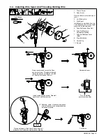
Page 17: ...rive Roll Release Lever Red 8 Wire Inlet Guide 9 Contact Tip 10 Nozzle Remove nozzle and contact tip Push and hold red lever Thread wire through inlet guide past push roll drive roll and out end of gun 2 inches 50 mm Release red lever Turn On welding power source power Install contact tip and nozzle Reinstall spool cover and thumb screw Wood Cut off wire Press gun trigger to feed wire to check dri...

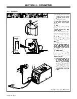
Page 18: ...actor start shielding gas flow and begin wire feed 5 Wire Feed Speed Control Wire feed speed is controlled by welding power source Wire Speed control see welding power source Owner s Manual or door chart for appropriatesetting 6 Voltage Control Arc voltage is controlled by welding power source Voltage control see welding power source Owner s Manual or door chart for appropriatesetting To purge shi...

Page 19: ...efore maintaining Maintain more often during severe conditions n Check Z Change Clean l Replace To be done by Factory Authorized Service Agent Reference Every 3 Months l Unreadable Labels Weld Terminals l Damaged Gas Hose nl Weld Cables nl Cords nl Gun Cables Every 6 Months OR Drive Rolls Inside Unit ...

Page 20: ... Roll To remove drive roll 5 Lower Drive Roll Screw 6 Washer 7 Lower Drive Roll 8 Drive Roll Key 9 Drive Roll Shaft Remove screw and washer and lift out drive roll Note drive roll key will come out with drive roll To install drive roll Place drive roll key in slot in drive roll shaft Line slot in drive roll up with drive roll key and slide drive roll onto shaft Secure drive roll with washer and sc...

Page 21: ...for proper weld output polarity connections see Section 3 3 Pressing gun feeder trigger does not energize welding power source welding wire is not energized shielding gas does not flow Secure plug from gun feeder trigger cord into 4 socket receptacle on welding power source see Section 3 3 Place Spool Gun MIG Gun switch in Spool Gun position see Section 3 3 Wire feeds shielding gas flows but weldi...

Page 22: ...et up to weld DCEP DC Electrode Positive S For MIG welding aluminum you need to use a 10 to 15 degree push travel angle tip and nozzle pointing in the direction of travel See Figure 5 1 10 15 Side View Of Gun Tip Angle 10 15 Direction Of Welding Forehand Push Technique Backhand Drag Technique Figure 5 1 Gun Tip Angle S Pulling or using a drag angle will produce porous dirty welds due to a lack of ...

Page 23: ...eshooting S Burn through melt through caused by over heating the base material 1 Increase travel speed Make shorter welds 2 Move around on part spreading out the heat 3 Use thicker material change joint design or welding process to AC TIG 4 Eliminate or reduce gaps S Dirty welds 1 Use push angle instead of drag technique 2 Increase voltage to get into spray transfer 3 Use proper base metal cleanin...

Page 24: ...OM 230 261 Page 20 SECTION 6 ELECTRICAL DIAGRAMS Figure 6 1 Circuit Diagram 186 451 ...

Page 25: ...OM 230 261 Page 21 Notes ...

Page 26: ...7 PARTS LIST Hardware is common and not available unless listed 804 699 A 3 2 30 26 29 31 27 15 28 25 24 23 18 17 16 13 11 10 4 9 8 7 6 5 4 2 1 42 39 40 41 38 37 34 35 33 32 19 22 21 20 12 14 36 43 44 Figure 7 1 Complete Assembly ...

Page 27: ...UIDE 1 24 048 834 CLAMP circ 1 25 079 878 CONNECTOR W SOCKETS 1 26 194 631 NUT brass 1 27 236 923 GEARBOX ASSEMBLY 3035 10 1 27 186 412 GEARBOX ASSEMBLY 3035 20 1 28 B2 236 922 MOTOR 3035 10 1 28 B2 186 417 MOTOR 3035 20 1 29 196 398 BUSS BAR interconnecting 1 30 197 570 ANTI ROTATION PIN 1 31 196 848 CONTACT ADAPTER 3035 20 1 32 234 348 HEAD TUBE ASSY 3035 10 1 32 196 849 HEAD TUBE ASSY 3035 20 1...

Page 28: ...Notes ...

Page 29: ...Notes ...

Page 30: ...Notes ...

Page 31: ... s 5 3 1 Limited Warranty shall not apply to 1 Consumable components such as contact tips cutting nozzles contactors brushes relays work station table tops and welding curtains or parts that fail due to normal wear Exception brushes and relays are covered on all engine driven products 2 Items furnished by Hobart Miller but manufactured by others such as engines or trade accessories These items are...

Page 32: ...utor retail or service location Call 1 877 Hobart1 or visit our website at www HobartWelders com Contact your Distributor for Welding Supplies and Consumables Options and Accessories Personal Safety Equipment Service and Repair Replacement Parts Training Schools Videos Books Technical Manuals Servicing Information and Parts Circuit Diagrams Welding Process Handbooks Contact the Delivering Carrier ...

Reviews: