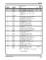
CHAPTER 4. ILLUSTRATED PARTS LIST
SECTION 1. INTRODUCTION
1. General
The Illustrated Parts List identifies, describes, and illustrates main assemblies, subassemblies, and detail
parts of the engine-driven generator sets manufactured by Hobart Brothers Company, Power Systems
Group, Troy, Ohio, 45373. These sets are identified as Hobart Series No. 6910, 6910A, 6910B, and
6910C.
2. Purpose
The purpose of this list is to provide parts identification and descriptive information to maintenance and
provisioning personnel for use in provisioning, requisitioning, purchasing, storing, and issuing of spare
parts.
3. Arrangement
Chapter 4 is arranged as follows:
Section 1 - Introduction
Section 3 - Parts List
Section 2 - Manufacturer’s Codes
Section 4 - Numerical Index
4. Explanation of Parts List
A. Contents
The parts list contains a breakdown of the equipment into assemblies, subassemblies, and detail
parts. All parts of the equipment are listed except:
(1) Standard hardware items
(attaching parts)
such as nuts, screws, washers, etc., which are avail-
able commercially.
(2) Bulk items such as wire, cable, sleeving, tubing, etc., which are also commercially available.
(3) Permanently attached parts which lose their identity by being welded, soldered, riveted, etc., to
other parts, weldments, or assemblies.
B. Parts List Form
This form is divided into six columns. Beginning at the left side of the form and proceeding to the
right, columns are identified as follows:
(1) FIGURE-ITEM NO. Column
This column lists the figure number of the illustration applicable to a particular parts list and also
identifies each part in the list by an item number. These item numbers also appear on the illustra-
tion. Each item number on an illustration is connected to the part to which it pertains by a leader
line. Thus the figure and item numbering system ties the parts lists to the illustrations and vice
versa. The figure and index numbers are also used in the numerical index to assist the user in
finding the illustration of a part when the part number is known.
OM-2028
May 1/91 Revised
4-1
Page 1
Summary of Contents for 6910
Page 2: ...This page intentionally left blank ...
Page 14: ...This page intentionally left blank OM 2028 Introduction June 20 89 Revised Page 2 ...
Page 40: ...This page intentionally left blank OM 2028 1 1 May 1 91 Revised Page 26 ...
Page 66: ...Engine Control Panel in Tilt out Position Figure 6 OM 2028 2 1 August 31 90 Revised Page 12 ...
Page 72: ...This page intentionally left blank OM 2028 2 2 June 20 89 Revised Page 6 ...
Page 128: ...Generator Set Figure 1 OM 2028 4 3 May 1 91 Revised Page 2 ...
Page 130: ...Canopy Assembly Figure 2 OM 2028 4 3 May 1 91 Revised Page 4 ...
Page 132: ...This page intentionally left blank OM 2028 4 3 May 1 91 Revised Page 6 ...
Page 134: ...Generator Set Without Canopy Figure 3 OM 2028 4 3 May 1 91 Revised Page 8 ...
Page 136: ...This page intentionally left blank OM 2028 4 3 May 1 91 Revised Page 10 ...
Page 138: ...Radiator and Cooling System Group Figure 4 OM 2028 4 3 May 1 91 Revised Page 12 ...
Page 142: ...Electric Governor Kit Figure 6 OM 2028 4 3 May 1 91 Revised Page 16 ...
Page 144: ...Fuel Lines Assembly Figure 7 OM 2028 4 3 May 1 91 Revised Page 18 ...
Page 146: ...Oil Line Assembly Figure 8 OM 2028 4 3 May 1 91 Revised Page 20 ...
Page 148: ...Stator Terminal Panel Assembly Figure 9 OM 2028 4 3 May 1 91 Revised Page 22 ...
Page 150: ...Power Module Panel Assembly Figure 10 OM 2028 4 3 May 1 91 Revised Page 24 ...
Page 152: ...Control Box Assembly Figure 11 OM 2028 4 3 May 1 91 Revised Page 26 ...
Page 154: ...Generator Controls Tray Assembly Figure 12 OM 2028 4 3 May 1 91 Revised Page 28 ...
Page 156: ...Protective Relays Tray Assembly Figure 13 OM 2028 4 3 May 1 91 Revised Page 30 ...
Page 158: ...Control Box and Internal Components Group Figure 14 OM 2028 4 3 May 1 91 Revised Page 32 ...
Page 160: ...Engine Control Panel Assembly Figure 15 OM 2028 4 3 May 1 91 Revised Page 34 ...
Page 162: ...This page intentionally left blank OM 2028 4 3 May 1 91 Revised Page 36 ...
Page 164: ...Output Terminal Board Assembly Figure 16 OM 2028 4 3 May 1 91 Revised Page 38 ...
Page 166: ...Generator Assembly Figure 17 OM 2028 4 3 May 1 91 Revised Page 40 ...
Page 168: ...Mounting Frame Assembly and Lifting Yoke Figure 18 OM 2028 4 3 May 1 91 Revised Page 42 ...
Page 170: ...Water Heater Figure 19 OM 2028 4 3 May 1 91 Revised Page 44 ...
Page 172: ...This page intentionally left blank OM 2028 4 3 May 1 91 Revised Page 46 ...
Page 174: ...This page intentionally left blank OM 2028 5 0 May 1 91 Revised Page 2 ...
Page 176: ...This page intentionally left blank OM 2028 6 0 June 20 89 Revised Page 2 ...
Page 177: ... I I I I I l zE I I 01 39NVN jlOVlQ t __ ...
Page 178: ......
Page 179: ......
Page 180: ......
Page 181: ......
Page 182: ......
Page 183: ......
Page 184: ......
Page 186: ......
Page 187: ......
Page 188: ......
Page 189: ......
Page 190: ......
Page 191: ......
Page 192: ......
Page 193: ......
Page 194: ......
Page 195: ......
Page 196: ......
Page 198: ......
Page 199: ......
Page 200: ......
Page 201: ......
Page 202: ......
Page 203: ......
Page 204: ......
Page 205: ......
Page 206: ......


