User Guide | FreeSpeak Edge Base Station
2.3
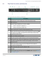
Rear Panel Connectors and Indicators
The rear connectors and indicators are listed below.
Item
Description
A
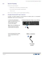
Internal power connector. Mains power lead with internal power supply.
B
Grounding screw.
C
General Purpose Input/Output connectors x2 (DB-9F).
l
GPIO 1 contains GPI1 and GPO1 & 2
l
GPIO 2 contains GPI2 and GPO 3 & 4.
D
XLR 2-wire Partyline connectors (standard microphone cable)
E
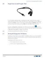
RJ45 4-wire audio and data connectors. Port 8 is dedicated to Program Feed (
PGM
)
and Stage Announce (
SA
), to be used with the split XLR cable connector that is
supplied with the Base Station.
F
Dect Sync RJ45 connectors, IN, OUT.
G
E1 RJ45 connectors to splitter/transceiver. Do not connect IP transceivers here.
H
SFP cage for E1 fiber connection to splitter/transceiver (Either single-mode or multi-
mode fiber modules. Modules must match existing cabling). Do not connect IP
transceivers here.
I
RJ45 LAN connectors. IP transceivers, the configuration PC and Dante are
connected here. Capacity 1GB.
J
SFP cage for fiber LAN connectors. Capacity 2.5 GB.
K
SA/PGM
L
External power supply connector (12V DC).
CAUTION:
Before using, see
Page 14
Summary of Contents for Clear-Com FreeSpeak Edge
Page 41: ...User Guide FreeSpeak Edge Base Station 5 1 Overview of Transceivers Page 41 ...
Page 45: ...User Guide FreeSpeak Edge Base Station Page 45 ...
Page 83: ...User Guide FreeSpeak Edge Base Station Page 83 ...
Page 96: ...User Guide FreeSpeak Edge Base Station Transceiver details Page 96 ...
Page 105: ...User Guide FreeSpeak Edge Base Station Page 105 ...


